
By Fred Boucher
with kit release history by Alan Bussie
Introduction
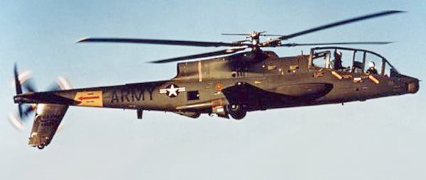
Your humble reviewer has been planning to present this model for years as the Cheyenne has always intrigued me. The AH-56 was an aesthetically odd helicopter designed in the aerodynamic transient era of rounded and squared contours. It had an airplane propeller for thrust and a great looking airframe behind a goofy looking canopy and nose that resembled a cartoon AV8 Harrier! Yet the machine was so fast that during test flights nobody had a helicopter that could keep up with it. Army aviation had to procure some refurbished WWII P-51 Mustangs to chase this raging rotorwing across the sky! The AH-56 was able to perform aerobatics and there are many minutes of AH-56 video available on the internet.
The AH-56 Cheyenne Story
AH-56 was designed to fit the requirements of the US Army’s Advanced Aerial Fire Support System (AAFSS) program (1964-71). The helicopter won the competition and the first prototype flew (unofficially) in September 1966. AH-56 was expected to enter service in 1968, but the program was terminated and the helicopter never advanced beyond prototype stage.
While the AAFSS was won by the Lockheed AH-56A Cheyenne, Bell had entered a scaled-down version of its Iroquois Warrior and the other competitor was the Sikorsky (S-66) (1964) which looked similar to the AH-56A Cheyenne, but had a Rotorprop tail rotor which could rotate on it’s axis through 90 degrees to act both as an anti-torque rotor or as a pusher, thereby transforming the S-66 into a compound aircraft in cruising flight.
Lockheed officially rolled-out the first prototype on May 3, 1967. The rigid-rotor Cheyenne, with a crew of two, featured a XM112 swiveling gunner’s station linked to rotating belly and nose turrets, and a laser range-finder tied to a fire control computer. It was armed with an XM52 30mm automatic gun in the belly turret and a XM51 40mm grenade launcher or a XM53 7.62mm Gatling machine gun in the chin-turret, TOWs, and XM200 rocket launchers. Ten prototypes were completed before the program was terminated August 9, 1972 due to delayed development, rising costs, and the appearance of the two competitive company-funded initiatives by Sikorsky and Bell. The Army wanted a smaller, more agile Advanced Attack Helicopter (AAH) with a less complicated fire control and navigation system. The helicopter’s mission would eventually be assumed by the Boeing (formerly McDonnell Douglas) AH-64 Series Apache attack helicopter. The Cheyenne had a single rigid four-bladed main rotor and anti-torque tail rotor, and a three-bladed pusher. It was powered by one General Electric T64-GE-16 3435 shp turbine engine and had a speed of 246 mph (214 knots).
Doug Marker Feb 2000 (with info obtained back in the 1970s from one of the original AH-56A designers)

Metric Data for AH-56A
Crew: 2
Main rotor diameter: 15.3 m
Wingspan: 7.9 m
Length: 18.3 m
Height: 4.2 m
Empty weight: 5315 kg
Takeoff weight: 7709 kg
Engine: 1xGeneral Electric T64-GE-16, 3435 hp
Max. speed: 386 km/h
Climb rate: 17.4 m/s
Ceiling: 7925 m
Range: 1400 km *
(Further history of the Cheyenne rotor system is at the bottom of this review.)
The only injection molded model of the amazing AH-56A Cheyenne helicopter is this 1/72 model by late-great Aurora. This review examines the vintage collector’s model.
Release History
By the mid 1960s Aurora was facing serious competition domestically from Revell and Monogram. The WWI line was still doing well, but every kit in the 1/48 WWII line had serious competition from far superior kits. Also, builders were maturing and demanding better detail. Aurora had previously cut molds as quickly as possible with little real data; this formula worked well for years but was now hurting the company. So in the late 1960s they began cutting new molds to a higher standard. The AH-56 was one of these kits. The first issue appeared in 1968 as kit number 502-150 in a ‘long box’ with dramatic artwork. The kit was molded in tan and clear. There is a Canadian issue that is almost identical. For it, Aurora added that the instructions were also in French and changed the kit number of 502 and omitted the price extension.
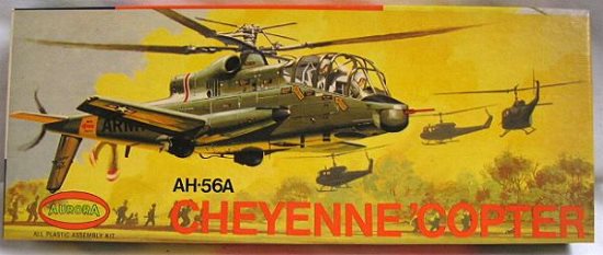
502-130 AH-56A Cheyenne ‘Copter ‘Long Box’
At this time Aurora was cutting back on kit production by removing the poor sellers. Since this was a new kit, it remained in the line-up. Surprisingly, Aurora changed the box art (which was very expensive to do) just one year later in 1969 for the square ‘Big A’ logo hardbox issue. The kit number remained the same. This version was issued for 3 years. The art created for this issue was also used on the “Young Model Builders Club” issue. A color paper label with the art was glued to a plain, brown cardboard mailing box and a bagged kit was placed inside.

502-130 AH-56A Cheyenne ‘Copter ‘Square Box’
Aurora changed boxes again in 1972, going to a much less expensive ‘soft box’ with the art printed directly on the cardboard. The old art was cropped and re-used. These boxes are much thinner and often turn up damaged. The part number was changed to 502.
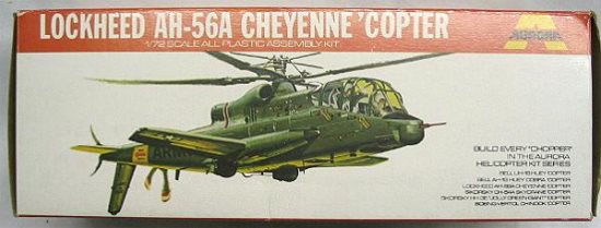
502 AH-56A Cheyenne ‘Copter ‘Soft Box’
As it turns out, the Cheyenne stayed in the catalog right until the end of Aurora in 1977. The box pictured above was used until the factory discontinued all model production.
In The Box
This example is a later ‘soft box’ issue released in 1976 per the date on the instruction sheet. The model is packed in an unusual rectangular end-opening box. The art shows a Cheyenne slicing low over an LZ, with that scene reproduced on the instruction sheet.
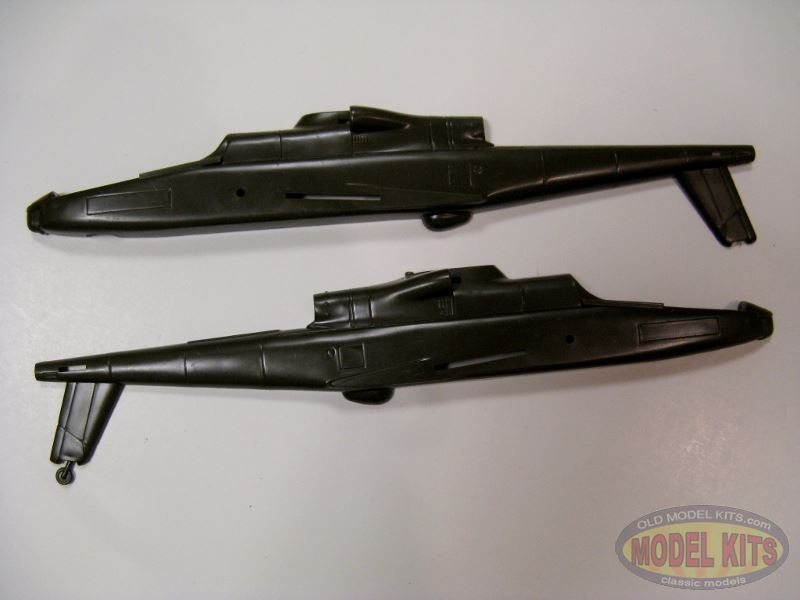
Inside are sprues of injection molded dark olive styrene and a clear canopy. The parts include:
36 x dark olive
1 x clear canopy
1 x decal sheet
1 x single-page instruction sheet
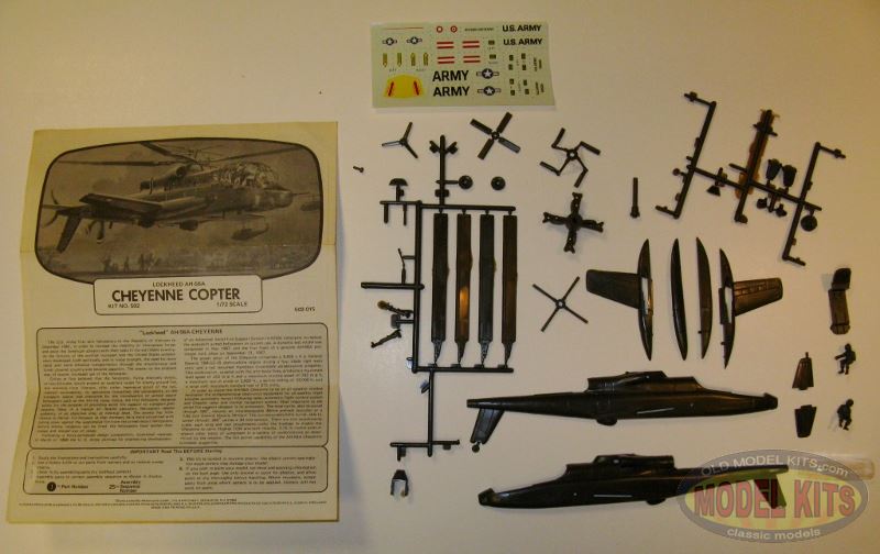
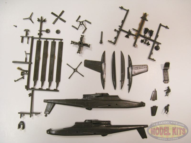


Kit contents and close-ups (click any to enlarge)
Aurora molding was good for the era and this model is typical. Their work was becoming substandard and by the mid-1960s they were cutting molds that were competitive with Revell, Monogram, Airfix, et al.. Some parts have flash and mold seam lines. Sink marks mar the nose of both fuselage halves, sponsons & wings, and other parts. Just as bad in my eyes are a few visible ejector circles, two of which ruin the canopy. It will require some careful sanding and polishing to fix those. That is a shame since the majority of the clear plastic is very clear and undistorted, with reasonable framing detail.
Otherwise the molding is pretty good for the era. This model has recessed panel lines, wide though they are, and while it does have some raised surface detail it is not festooned with rivets. (Not that raised rivets are inaccurate on oh-so many subjects.) By the time Aurora injected this model they had discontinued machining insignia into the exterior of the model. The parts are fairly thick, even trailing edges.
Even though the Cheyenne was cancelled, it went through extensive AGM (Air to Ground Munitions) testing. Aurora left this model unarmed except for the 30mm chin cannon.
Detail
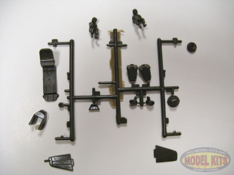
Most of the parts are thicker than scale. The undercarriage is quite robust with little detail for the wheels. That may be good as the gear is made to be retractable. Other “action” features trumpeted by Aurora on their box were: Rotating main and tail rotors and pusher propeller and moveable minigun and belly turret.
Aurora eschewed almost all cockpit detail except for the instrument panels. They gave raised detail for the bezels and dials. So much for “Fully detailed cockpit” as proclaimed on the box.
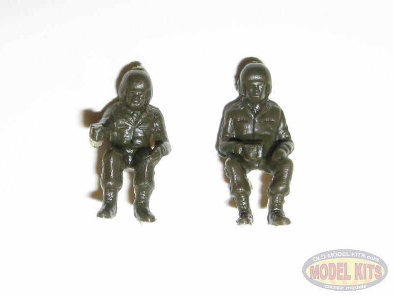
The pilots have decent albeit soft detail, although the heavy flight suits and equipment vests can excuse this.

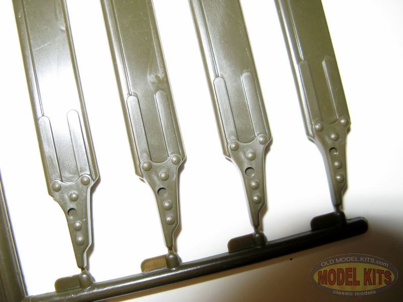

Parts Details (click any enlarge)
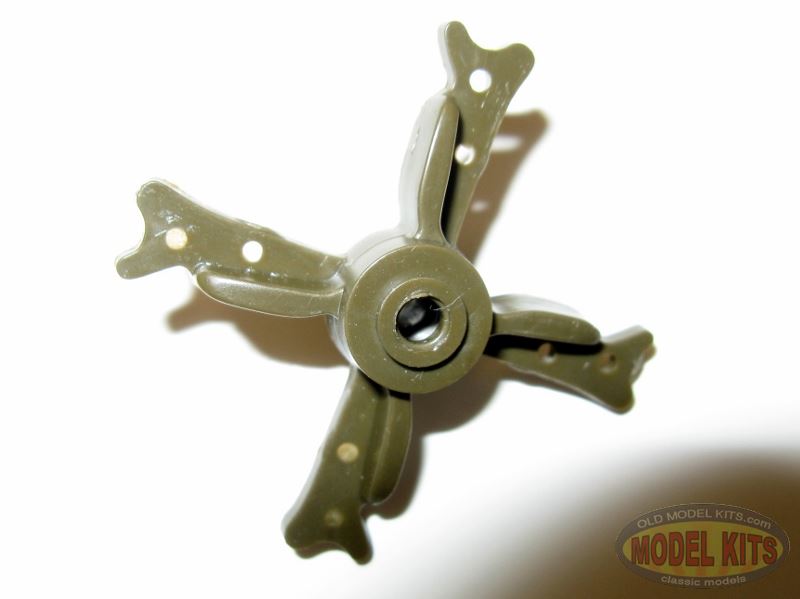
Rotor detail is…well, I’ll let the photos do the talking and you ‘copter fans the critiquing.
Airframe exterior detail is sparse and Aurora forgot to tool detail such as ventilation louvers for APU and avionics bay ports.
The canopy is inaccurate as the real deal was bulged at the top to afford the crew better downward visibility.


Parts Detail (click any to enlarge)
Instructions, Decals, Painting
A single piece of paper is the instruction sheet and model history. It guides you through assembly in three steps of exploded-view. The model history is amusing. While the sheet was printed in 1976 it retains the original box art and the original Aurora history of the AH-56A, writing of the aircraft in present tense; apparently nobody thought about changing the text to reflect that the Cheyenne was cancelled years earlier. A copy of that history is at the bottom of this review.

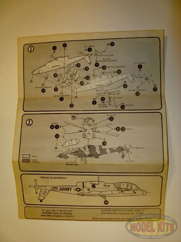
Instructions (click to enlarge)
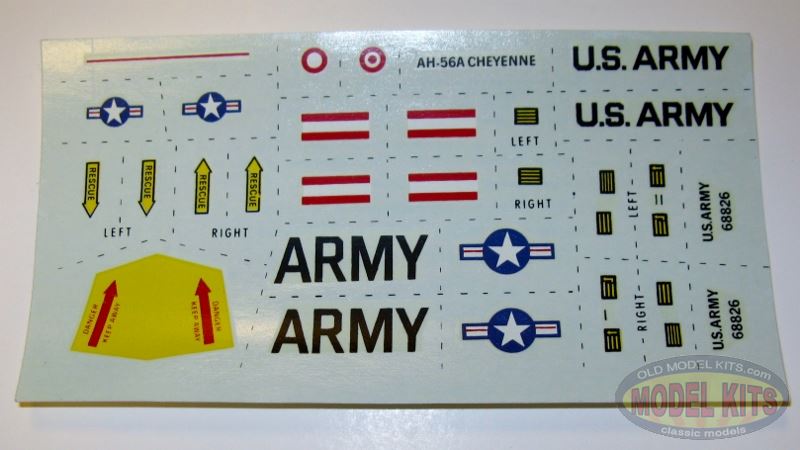
Decals are adequate. Even after decades they are not yellowed which is convenient as the carrier film is generous. They are sharply printed but some are off registration. It appears that the national insignia blue is light. Only one airframe is represented,”No. 68826”. That belonged to the second airframe, actually serial number 66-8826, and was a flightless test variant for proving the rotors and engine.
Painting directions are sparse, guiding the modeler with a three-color pattern of olive, tan and light gray. Oh, and some silver, black and grays.. .
Conclusion
This is a vintage model from a defunct manufacturer. It is a fair model by today’s standards, featuring recessed panel lines, some molding flaws and an adequate decal sheet even if they lack today’s precision. I don’t have a 1/72 template to check the profile against although it has some obvious mistaken contours, the canopy for instance.
Highs: Recessed panel lines.
Lows: Lack of cockpit detail. Flash, sink marks, ejector circles, mold seam lines.
Verdict: It can be built into a decent model as demonstrated by many examples you can view on the web. I think it is a fun model to have whether for building or collecting.
All the same it can be built into a decent model as demonstrated by many examples you can view on the web. It is ripe for detailing. I think it is a fun model to have whether for building or collecting. I built one long ago that was molded in tan and I still have a part or two in a spare parts drawer. If you can find one I recommend snaring it for your collection of whirlybirds or just for nostalgia!
Aurora’s AH-56A History (with Aurora punctuation and mis-spelling)
“Lockheed” AH-56A CHEYENNE
The U.S. Army first sent helicopters to the Republic of Vietnam in December 1961, in order to increase the mobility of Vietnamese forces and assist the American advisors with their tasks in the warridden country. As the ferocity of the conflict increased and the United States commitment developed, both politically and in troop strength, the need for more rapid and more effective transportation through the mountainous and forest covered country-side became apparent. The answer to the problem was, of course, increased use of the helicopter.Critics at first believed that the helicopter, flying relatively slowly, at low altitudes, would present an excellent target for enemy ground fire, but statistics from Vietnam, offer rather impressive proof of the helicopters’ survivability. As operations intensified, the vulnerability of the transport copter was overcome by the introduction of armed escort helicopters such as the AH-1G Huey Cobra, the first helicopter designed solely for the purpose of providing aerial fire support to transport helicopters. Now, in a typical air mobile operation, helicopters appear suddenly in an objective area, at tree-top level. The enemy has little chance to deliver fire becasue, at that moment, he is more concerned with taking cover against the suppressive fire from the armed escort helicopters. Before enemy weapons can be fired, the helicopters have landed their troops and moved out of range.Following a hotly-con tested design competition, Lockheed received in March of 1966 the U. S. Army contract for engineering development of an Advanced Aerial Fire Support System (AAFSS) helicopter to replace the makeshift armed helicopters in current use. A dynamic test model was completed in May 1967, and the first flight of a genuine AH-56A prototype took place on September 21, 1967.
The power plant of the Cheyenne comprises a 3,435 s h p General Electric T64-GE-16 shaft-turbine engine driving a four blade rigid main rotor and a tail mounted Hamilton three-blade variable-pitch propeller. This combination, coupled with the trim body lines, produces a maximum level speed of 253 m p h and a maximum cruising speed of 242 m p h, a maximum rate of climb of 3,420 ft., a service ceiling of 26,000 ft, and a range with maximum standard fuel of 875 miles.
In order to insure the AH-56A Cheyenne to be an all weather combat helicopter the compreshensive electronics equipment for all weather flight includes automatic terrain following radar, automatic flight control system and Doppler radar and inertial navigation system. Most important to the aerial fire support chopper is its armament. The nose turret, able to swivel through 180˚, mounts an interchangeable 40mm grenade launcher or a 7.62 mm General Electric Minigun. The nonretractable belly turret, able to swivel through 360˚ carries a 30 mm cannon. There are two attachments under each wing and two attachments under the fuselage to enable the Cheyenne to carry Hughes TOW anti-tank missiles, 2.75 in rocket pods or several other types of armament in a variety of combinations as determined by the mission. The fire power capability of the AH-56A Cheyenne is indeed, staggering.
Gee-Whiz stuff: The Cheyenne rotor system (with grammatical and spelling errors)
The Cheyenne had a most remarkable (if not the most remarakable ]) rotor system. The techniques employed for tilting the rotor were (and remain) unlike anything ever devised.
If you look at the pictures you will see what amounts to a simple gyroscope just above the rotor. This gyro being the 4 ‘weighted arms’ that were a single unit mounted on a gimbal and which spun with the rotor. This gyro was used for two purposes :-
* To provide a stabilizing mechanism (not dissimilar the the famous ‘bell-bar’ gyro)* To directly change the angle-of-attack of the (rigid) rotor blades. The gyro had direct links to the blade pitch horns (these can be seen in some of the pics). So the *only* way to change pitch of the rotor blades was by causing the upper gyro-gimbal to tilt in what ever way it could be made to tilt (or in moving the gyro-gimbal vertically if collective pitch changes were commanded).Inside the body of the helicopter was the equivilent of a ‘swash-plate’, the inner ring had 4 control rods that ran up the inside of the rotor shaft – in the picture you will notice that the rotor shaft is short and quite thick – the control rods were directly coupled to the gimbal mounted gyro.
To explain this part of the control system, picture a conventional style swash-plate at the bottom of the rotor shaft. It has an inner and outer ring just like any swash-plate does. At the top of the rotor shaft, picture the gyro-gimbal. The gyro-gimbal in this example resembles a swash-plate in that it can tilt in any direction but, unlike the swash-plate, it has no seperate inner & outer rings that turn independantly. So the gyro-gimbal can tilt but will only spin with the main rotor shaft.
When spinning, the weighted arms become a gyro and of course this gimbal will now resist any tilting force at the point it is applied but will tilt 90 degrees further round in the direction of rotation, and this tilting will be in proportion to the continued force being applied at the original point.
So while the rotor was not spinning, if you were to tilt the lower swash-unit the gyro at the top would tilt in exactly the same directions, it would track the lower swash-plate exactly, but while the rotor was spinning, gyroscopic force would take over and prevent tilting both the upper gyro-gimbal and the lower swash-plate coupled to it, at the point the tilting force was being applied.
This is due to the tilting force being resisted by gyroscopic-precession from the upper gyro-gimbal. Of course this resistance is not there when the rotor (& thus gyro-gimbal) is not spinning.
The amazing part of this whole assembly then is what happened with the lower-swash unit and the upper gyro-gimbal it was coupled to, when the rotor was spinning, and also what actually happened when a tilting moment was applied to the lower swash-plate. The bit we are missing to this point is how the internal tilting control rods that go from the pilot’s servos to the lower swash-plate outer ring were physically connected.
Remembering that there are 4 control rods inside the rotor shaft linking the inner race of the lower swash-plate to the upper gyro-gimbal, we now add 4 more control rods, but these go from from the pilot’s cyclic servos to the lower swash-plate outer-ring and are connected to it with spring loaded rods. Because of the springs, each pair of these cyclic servo control rods could move against the swash-plate outer ring and and apply a force without the swash-plate having to tilt at the point the spring pressure was applied.
While the swash-plate would not actually tilt at the points the force was applied, the force or spring pressure was still transmitted up the rotor-shaft control rods to the gyro-gimbal at the top which was of course providing powerful resistance (due to gyroscopic-precession) to the applied force.
Being a gyro, the gyro-gimbal would tilt 90 degrees further round in rotation. So the gyro-gimbal at the top precesses and then because of the direct links back down to the lower swash-plate unit, the swash-plate unit would then be forced to tilt in the same direction as the upper gyro-gimbal and this was possible because the lower swash-plate could force itself against the springs on the spring loaded cyclic servo control rods.
Also the upper gyro-gimbal’s links to the rotor blade pitch horns, would cause the blades to change pitch. As it was a rigid rotor system and taking into account gyroscopic precession forces, the change in blade pitch would cause the whole craft to tilt 90 degress later than maximum (and minimum) pitch.
So if we look again at the chain of events needed to tilt the craft forward it was … that the lower swash-plate would have a moment or ‘force’ applied at its’ rear from the spring loaded rods connected from the pilot’s servos to the outer, non-turning part of the lower swash-plate. Because the swash-plate was directly coupled to the upper gyro-gimbal, it would follow the behaviour of the upper gyro-gimbal and would not tilt with the applied force but resist it. The springs pushing on the swash-plate outer ring would compress as the pilot pushed the cyclic stick forward.
The spring pressure force would in turn be ‘transmitted’ up through the control rods that are inside the rotor-shaft and apply the force at the *back* of the upper gyro-gimbal. The upper gyro-gimbal then behaved like any gyro and precessed 90 degrees later and this of course caused the other pair of internal control rods in the rotor shaft to push down to the lower swash-unit at this later 90 degree position.
At this position the lower swash-plate would tilt. To do so the lower swash-plate outer ring would push against the springs on the other pair of servo to swash-plate control rods.
Restated, because the pilot’s servo to swash-plate control rods were spring loaded, the springs that were 90 degrees further from where the original spring load or ‘force’ was being applied, would ‘give’ under the precessing push coming back down thru the internal rotor control rods from the upper gyro-gimbal unit.
The pilot, by pushing forward on the cyclic stick applies a spring loaded force up at 180 degrees & down at 0 degrees on the outer-ring of the lower swash-plate. The force is ‘transmitted’ up the rotor shaft through the control rods inside it that couple the swash-plate to the upper gyro-gimbal, the gyro-gimbal precesses and as it does so, does 2 things, one it directly tilits the rotor blades, and 2 pushes back down thru the control rods in the rotor shaft, to tilt the lower swash-plate in unison with itself. The lower swash-plate can tilt at this position because it is able to push against the other pair of spring loaded servo-to-swash control rods that are at the 90 & 270 degree positions.
Thus in final summary, the tilting push began 180 degrees before the actual tilt occurs as to tilt the helicopter forward, the pilot’s cyclic servos apply a spring-loaded force at the 180 and 0 degree positions on the outer non-turning ring of the lower swash-plate. The swash-plate, because it is coupled to the upper gyro-gimbal physically tilts at the 90 degree (port) & 270 degree (starboard) positions. The upper gyro-gimbal which through gyroscopic precession, caused the 90/270 tilt, also applies maximum and minimum pitch to the rigid rotor blades at the 90 & 270 degree position – because the craft has a rigid rotor and due to the effects of gyroscopic precession, the whole craft tilts at the 0 degree (nose down) and 180 degree (tail-up) positions. The tilt of the craft is totally due to gyroscopic precession. This of course is not what tilts a rotor system that is not rigid, i.e. has free teetering blades.*
________
Sources
* Doug Marker. Lockheed Cheyenne AH56. https://www.internetage.com/cartercopters/pics9.htm. 12 Feb 2000.