
By Alan Bussie & Ken Friend
We are happy to announce that Oldmodelkits.com has received exclusive license from the French Line to produce and sell the 1/350 SS Normandie Ocean Liner model kit! The first batch are ready to ship. These are limited run kits in resin with photoetched details.
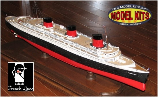
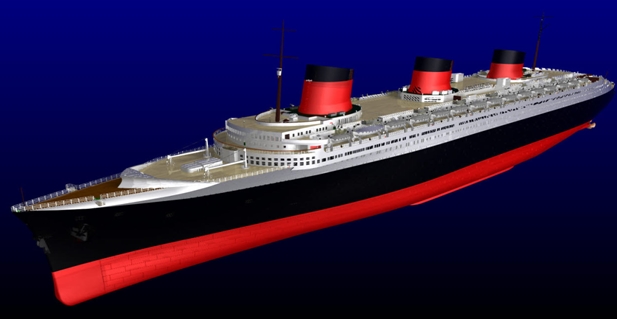
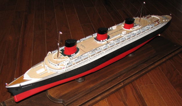
Photo of the first production model, built by Ken Friend
If you have ever wondered what goes into making a model, then please read on! If you plan on buying a 1/350 Normandie, please continue so you will know what went into your personal model.
Alan: In 2007 Ken Friend and I decided to make a model kit. It was not a sudden decision, but the result of two life-long dreams. I had been seriously investigating making a number of unique models but I lacked certain necessary skills. Ken had wanted to produce a model also and did possess the numerous skills that I lacked- IPMS National Award Winner, CAD expert, early 3D printing engineer for GM and a mold maker/caster.
Ken: On February 21, 2007 I received this email from Alan Bussie who owns the company named “Old Model Kits.” Alan and I had been discussing how to convert ship model drawings to actual ship model kits. Alan’s approach was typical for the time; one-offs with handmade parts. I suggested using some newer technology that would allow him to create a kit he could market through his OMK business. The following email was the start of a 9+ year project that resulted in the production of the 1/350 Normandie ocean liner as she was originally constructed-
Hello Ken
Wow, how exciting!
Let me briefly share with you what this is all about.
As you know, I have a love of passenger ships. The Titanic is not my favorite ship, but it’s the only large scale (if 1/350 is large) model that I could buy. About 5 years ago I got it in my head that if I could 1. Get a data file for the hull, block superstructure and funnels, then I could run them on high-end woodworking equipment (Slick hulls – not lapped- with only porthole detail would be a dream come true) AND 2. I could make doors, glue-on superstructure sides, etc from photoetch brass with Adobe Illustrator and any job shop for photoetch (or laser now) AND 3. If the ship was a common scale, such as 1/192 or 1/350, I could buy winches, props, booms, lifeboats, davits, etc from fittings shops such as Bluejacket, etc. Pre-scribed lumber from Northwestern would make the wooden deck planking easy.
I had gotten as far as ordering wood, fittings samples and trying my hand at the photo-etch drawings. Then life got in the way, darn it. So there it was…1/350 or giant 1/192 creations of models that have never been produced, that could be done fairly easily! How realistic it is has yet to be seen.
I packed up the plans for the NORMANDIE and the BREMEN and they will go out tomorrow. I don’t need the plans anytime soon, so no worries. I did insure them as they were not cheap. The NORMANDIE plans are huge. There are two sets, one large and one small. The BREMEN is just medium sized. The NORMANDIE is my first choice unless BREMEN looks easier.
Sincerely, Alan
Alan: So Ken and I set our goals:
- To research the Normandie tirelessly
- To make the model as accurate as we could
- To use the best technology available to us
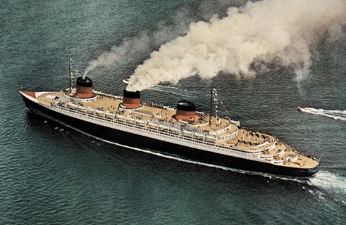
Normandie in a rare pre-refit color photo
My job was primarily research & capital, and helping with anything that Ken needed, such as outsourcing, materials, etc. Yes, believe I got the easier end of the bargain but researching the SS Normandie took 7+ years and was generally a nightmare. Everything was more difficult because the ship had a very short service life before being sunk. As it turned out,
- Readily available information and plans were very incomplete, limited or simply incorrect
- Details impossible to discern from plans presented great challenges
- The CGT altered the Normandie constantly and she was truly a ‘work in progress.’ For example, the number of changes between fitting out, sea trials and the maiden voyage are staggering. Beyond that the changes accelerated even faster.
- Of the dozens and dozens of custom-built models known at that time, all had significant inaccuracies.
- The old Ideal Aeroplane & Supply large-scale kit (1930s) and the modern $3000+ display models proved to have no value for accurate research purposes
- Cardstock models proved to be very error-prone or over-simplified
The conflicting information resulted in such massive confusion that a research criteria was needed. I decided that:
- The occurrence of each detail must be verified by at least one piece of photographic evidence from the correct time frame (i.e. maiden voyage)
Once this criteria was set, there were numerous problems. Because of the 6 points above, the criteria was impossible for a numerous critical details. But knowing the confusion and inaccuracy surrounding the ship, we refused to compromise the research criteria. Progress was very slow and we had more questions than answers. At times it looked impossible, but Ken and I refused to give up.
Ken: From the drawings we had, it was obvious that the basic hull contours could be readily verified through the cross-sections of the ship. The basic hull and superstructure were 3D modeled and readily visible details such as portholes, hull panel lines, and window detail were added. The hull was divided in sections that would fit on the 3D Printer’s table, and the whole ship 3D printed; a process that took 20 hrs to complete. Then Alan went on vacation and found the 12 foot long Normandie model in the museum on the RMS Queen Mary……
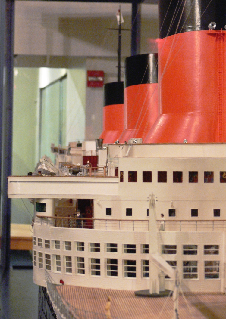
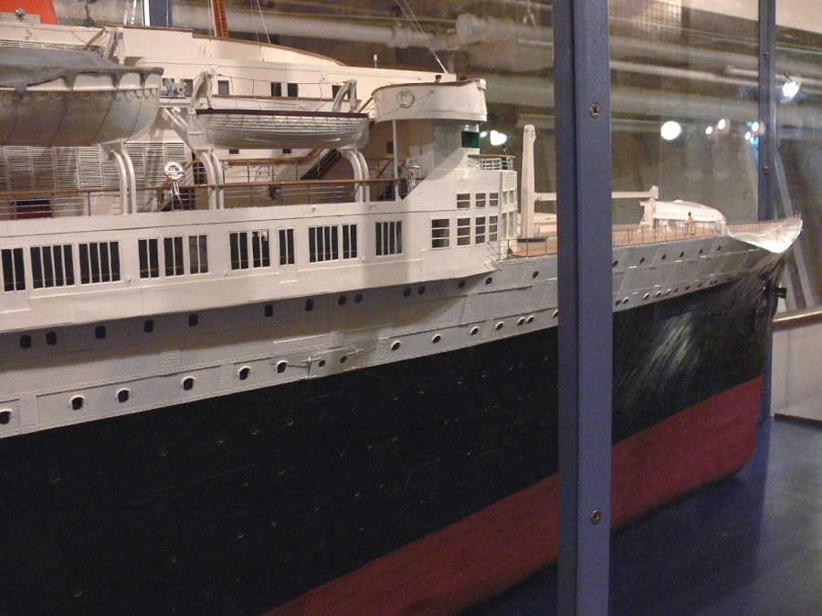

Normandie Model on the Queen Mary (click any to enlarge)
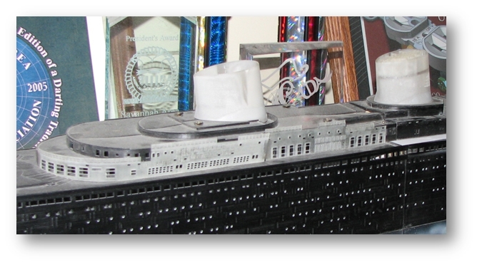
Alan: This model of the Normandie is located inside the Queen Mary at Long Beach, California. This ‘discovery’ (so to speak- it had been there for years!) was about 2 years into the research.
Once ‘discovered,’ we did not know if it was accurate. I initially (and incorrectly) guessed it was an inaccurate, huge, custom-built 3D copy of the famous French Line advertising cut-away fold-out from the 1930s. That drawing is beautiful but very inaccurate. But differences popped up immediately, proving the two were completely separate. Of course the ‘discovery’ of this information caused a minor re-design of much model! As frustrating as this was to us both, it was a huge relief to know that details could be confirmed.
Ken: The superstructure details were wrong on our 3D master. Rather than reprinting the whole superstructure, the detail was removed from the master and replaced with 3D printed “wraps” of the correct detail. The detail was recreated in 0.010″ high material on a 0.005″ thick base.
Alan: Over the next 5 years of research, the details of ‘The Queen Mary Model’ (as we began calling it) were verified one-by-one against many hundreds of photos, negatives from the ship and screen-captures from movies. I can’t tell you how many times we spotted something on the ‘Queen Mary Model’ that flew in the face of accepted knowledge…and upon further investigation, the detail could be 100% verified with photos of the ship. One myth after another was ‘busted’ and ‘The Queen Mary Model’ became an invaluable (but always verified) resource.
The accuracy of ‘The Queen Mary’ model is so phenomenal that Ken and I often wondered who the modeler was. Clearly he had more modeling information than anyone has ever had (or will have) on this liner. Additionally, his execution was superb. Now, thanks to James Luckard, we know who the modeler was – Father Roberto Pirrone of California. Here is a link shown the model and the amazing interior spaces –
https://www.encyclopedia-titanica.org/community/threads/normandie-super-model.26052/
As modelers know, research is an on-going process. As a kit is built or designed, every answer inevitably leads to more questions. Those answers lead to more questions. The ‘rabbit hole’ is long and deep and you have to be ready to go down as far as the information can provide. Ken and I know that we did as good of a job as could be done with all the information available. However, one day more information will become available and it is our hope that someone will build upon this work to make an even more accurate model.
Rivet counters will note there are imperfections in the model. I’ll give a few examples:
- We have a very close count of how many decking planks were across the Normandie amidships. However, in 1/350 scale the laser and/or printer cannot accurately portray them and either can the human eye. So, like most all scale ship models, the planking is a representation.
- We had an accurate count of the drain holes on the edge of the decking; however, the same problem arose. So should we include them or not? For the sake of detail, we included them at a lower count
- On many occasions, other details were too small for 1/350 scale. We decided to reproduce them anyway for the sake of accuracy, provided that it looked convincing. For example, this is a riveted-hull ship; but rivets are not shown. In 1/350 scale we could not reproduce them and have them look ‘good.’
- There are limitations to the photo-etching process that limit the height and thickness of parts. So some PE parts are ‘necessarily’ out of scale
- We did not have close-up photos of every section of the hull, so the hull plating detail is approximated
Ken: The Virtual Design Process (Art): Utilizing the “Best Technology” concept began with a what is called “art-to-part.” This concept begins by creating a three dimensional virtual model in CAD and “printing” the 3D components through stereolithography. This 3D printed parts created masters that could be molded for resin part duplication. The resin parts were then kitted for other model builders.
Two sets of plans for the Normandie were available; one in 1/192 scale and one in 1/350th scale. Both sets of plans were taken to a local blueprint company and scanned into JPG images. The resulting images were then cut into smaller graphics sections for use within TurboCAD, i.e.; cross-sections of the hull, detail views, etc.
The section profiles were brought into TurboCAD and placed on their own layers. These were re-scaled to the proper sizes and checked for the proper aspect ratio and dimensions. Construction planes were created at the stations indicated along the profile view of the hull, and each section traced onto the proper plane with b-splines. This process generated the foundation for the creation of a 3 dimensional model of the hull.
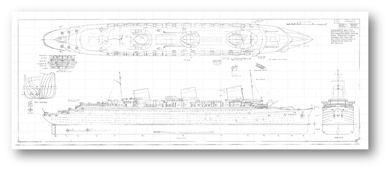
Plans for the SS Normandie and Hull sections (click to enlarge)
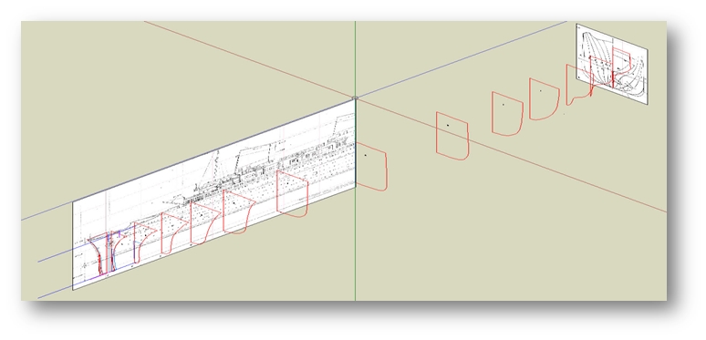
This scanned image was broken into individual components and brought into TC on the appropriate work planes.
Hull Templates View (click to enlarge)
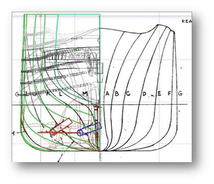
When lofting between sections, several errors and deformed contours were found. Through the help of the those on the TurboCAD Community forum (after I was told I was “NUTS” for trying to build a ship in TC), it was suggested that I tried copying the largest section spline to the other work planes then adding the lofting. It was thought that the varying numbers of nodes on the original splines was causing the difficulty. This corrected many of the problems, but I still found that any edited splines were extremely sensitive to their control point location(s). The common error during lofting was “self-intersecting.”
The complexity of the overall model started to push the 32 bit TurboCAD software to the point of non-functionality. It was about this time in the process (2009) that an on-line design competition was held for TurboCAD designers. Unfortunately, the 32 bit architecture limited my entry to only the stern of the Normandie. However, the model won an award and I became a “beta” tester for IMSI as part of the award.

Visualization of Normandie Stern Section project and Award for same (click any to enlarge)
Once the sections were established, the profiles were used to “loft” a solid to form the hull contours. The hull solid was “shelled” to provide a uniform wall thickness and minimize material.
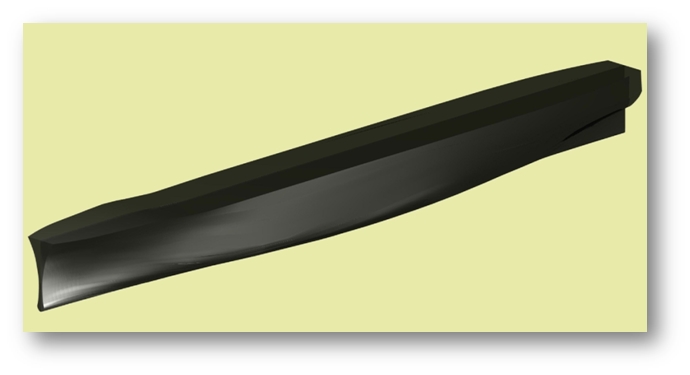
Main Hull Solid and Port Hole Mirroring (click to enlarge)
348 portholes were added to the port hull by extruding the various porthole shapes through the hull and then subtracting them from the hull solid. The port side was “mirrored” to create the starboard side.
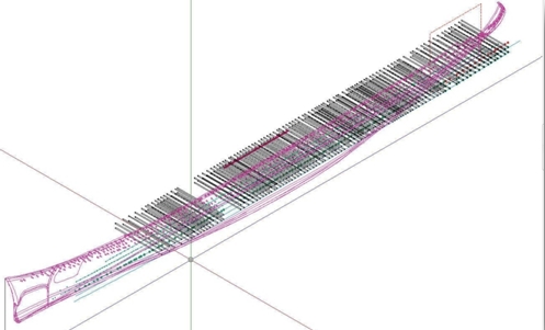
Alan requested that we take a look at adding panel lines to the outer hull to simulate the plates used to construct the original ship. Adding panel lines to the irregular hull contours required a non-standard approach. Once again I contacted the users on the forum, and once again learned that most thought I was totally “NUTS.” Too late, I was already working on the first of 515 blocks…

Hull Plate Grid Used to Extrude Through Hull Solid and Final Plating (click any to enlarge)
Panel line creation for the plates in the hull was accomplished by extruding rectangular and polygonal plate shapes through the hull solid and “intersecting” those solids to form a “Lego” type block in the shape of the ship’s contour. The outer edges of each block were rounded with a 0.020″ radius. The blocks were then “added” back together to reconstruct the hull; the rounded edges defined the panel lines.
Software Issues: The model was becoming very complex, and the file size was increasing rapidly. I started having out-of-memory problems and/or system crashes. I was really concerned that the project was in jeopardy. So back to the forum… and I began to research hardware configurations and what others were using. Even though I was using a Core 2 Quad processor with 2GB memory and an nVidia Quadro FX1500 on 32 bit Vista, I thought a hardware upgrade might help. My first step was to increase system memory to 4GB; but it was no help.
Through my conversation with the user forum folks, I learned the 32 bit limitation on memory usage had become a focal point for all the beta testers. I bought a new disk drive and loaded Vista 64 bit. I also went to 8GB memory just to make sure hardware and operating system weren’t the limiting factors. NOTE: I emailed the IMSI Technical Support folks and was told TC would NOT run under a 64 bit operating system. I did it anyway. I found that TC actually was more stable in the 64 bit environment then it had been in the 32 bit environment, and I could even run other processes in background without having TC crash out as it had before (whenever a new email came through or Windows Update kicked off.) In both the 32 bit and the 64 bit environments performance was never an issue. However, I still reached the point where the out-of-memory message would end my session. Shading was impossible unless I turned off every usable feature offered in TC; and then only low-resolution images were available.
IMSI and 64 Bit Software: I received a phone call from Dave Taylor, Project Manager for the TurboCAD product line, asking for permission to use the Normandie file as a development tool and training for IMSI. Permission was granted to IMSI for the use of the Normandie model in training classes around the world as an example of large file capabilities and manipulation. As such, the Normandie design file became an instrumental tool for the IMSI development group as the beta tester push for 64 bit software evolved. As the 64 bit software evolved, the whole Normandie file could be displayed in wireframe and/or shaded imagery. The extreme details such as panel lines, rigging, and railing could now be added to a complete model.
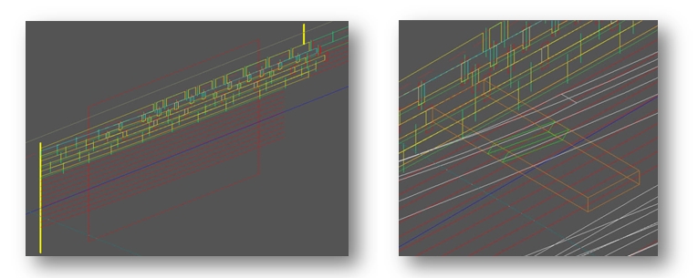
Real Wood Decks: Originally, the decks of the master hull model had 0.030″ high lips that surrounded the areas that would be wood. At the time of the design work, real wood decking was about 0.030″ thick. Newer technology reduced decking to about 0.008″ thickness. It was decided to fill in the wood deck areas in order to use the newer offerings. The wood deck areas were filled with 0.030″ material to make them flat. Decking geometry for the deck manufacturer was created by laying a thin solid over the areas to be covered with wood. The hull structure was then “subtracted” from the thin solid.

Wood deck templates created from superstructure overlays (click to enlarge)
Detail parts created from ACIS solids (click to enlarge)
The Details: 3D Printing (to Part): About this time I went to the International Plastic Modelers Society (IPMS) national competition, and met the folks from FineLine Printing. I talked with them about the Normandie project and what limitations we would encounter with stereo lithography. Our model would be over 36 inches in 1/350 scale; FineLine’s biggest machine could only handle 29 inches. It was a blessing in disguise. I had to split the model into fore and aft sections to fit the machine. I could now work on the individual sections instead of the whole mode, and could now do more detail work on the individual parts without encountering the OOM as often. More detailed shading of the individual sections was now possible.
The change also created an opportunity to rethink some of the project and to reorganize the parts a little better. I was still working in 1/192 scale and needed to get the parts into 1/350 scale. It was with great relief that I was able to easily rescale all the complex models from 1/192 to 1/350 in TC and simply pick up where I left off. I finished the panel line details and started to work on getting sample files ready for FineLine.
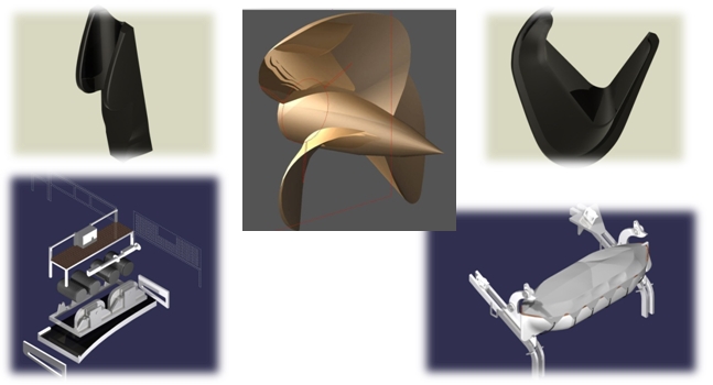
It was time to convert the 3D files into real parts. Three methods were evaluated: powdered stereo lithography, laser/liquid polymer stereo lithography, and ABS plastic extrusion stereo lithography. We had originally considered 3D powder printing, but after getting some sample parts found that the detail capabilities would not meet our needs. We then tried an ABS printout. The best resolution the vendor’s machine could generate was 0.010″ layers. Nice parts, but the steps interfered too much with the detail of the model.
FineLine had done some sample liquid polymer STL parts for us that showed the detail that would be required for our smaller parts. We knew this process would be too costly for the larger parts, but learned that FineLine had a myriad of other processes we could possibly utilize. We sent them another sample, this time from the hull, and had them run an ABS type material. Their resolution was 0.004″ per layer. The ABS method proved to be the most cost effective and had good detail.
Various Printing Methods (click any to enlarge)
Powder Liquid/Laser
ABS 0.010″ Layers ABS 0.004″ Layers
Creating the Masters: Most of the parts for the kit were now designed and ready to send out for printing or photo-etching.
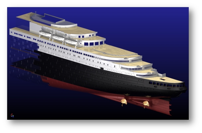
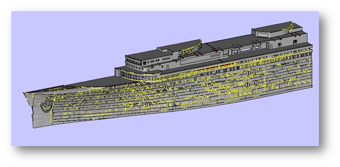
The near complete computer model (click to enlarge)
Creating a stereo lithography file was a simple matter of performing a “File, Save As” function with the TurboCAD software.
During the search for an STL printing vendor, some of them responded with “Your file is unusable.” Others said they had to correct errors before they could use the files. We asked the ones who made corrections about just what they had to do to get usable files. The response was usually “we had to reorient vectors.” Since there was no way to correct this problem in TC, I wanted to go further to see if I could find a utility that would let me see the errors, and if possible correct them before we sent out the files. The folks at FineLine said they use a tool called MiniMagics and that the STL file viewer was free to download. The viewer was a view only application, and would not allow correcting the files until the whole $3,000 package was purchased. Those vendors who could not work with the original files had no capability for providing the correction service. Those who quoted our parts provided the service for free. This image shows errors that occurred during the transformation of the hull file from a TurboCAD file to an STL file.

(click any thumbnail to enlarge)
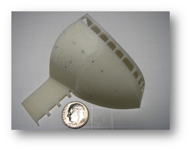
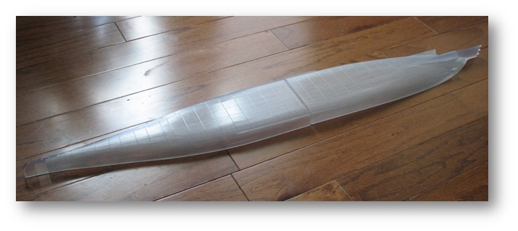
The Normandie hull was divided into 6 main sections. The complete port side hull was first sliced slightly above the waterline to provide the modeler with the option of making a waterline model or a complete ship. Each of the sections was sliced in half to allow FineLine to fit the parts onto their printing machine. The final “printout” of the 6 hull pieces was done at the same time and took 20 hours to complete.


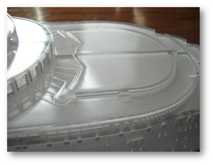
Normandie hull sections after 3D printing (click any to enlarge)
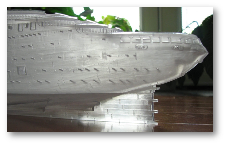
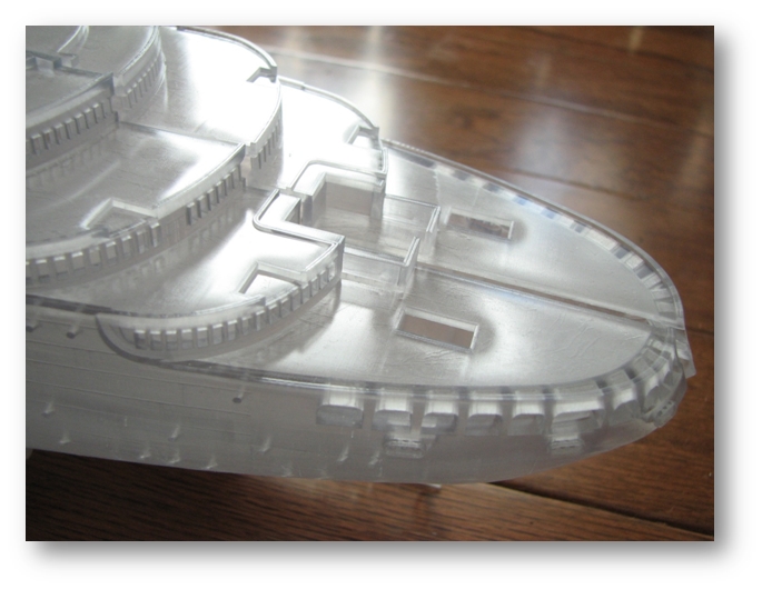
Close-ups of printed hull (click any to enlarge)
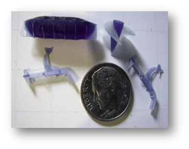
The creation of the smaller detail parts required two totally different methodologies. Many were flat and/or bent, others had compound curvatures and irregular shapes. Stereo lithography was used again for the complex shapes and photo-etching was used for the standard shapes that could be either used as-is or be bent to their final configuration.
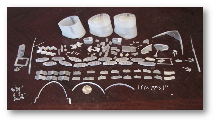
3D printed small parts (click to enlarge)
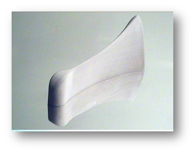
During the process of designing the myriad parts, errors in hull details were found. New images (from the Normandie model on the Queen Mary and photos) were utilized to correct the details on the 3D printed master. This required removing all of the superstructure detail and making new thin “wraps” to reinstate the detail to the correct configuration. These wraps were very delicate and only 0.005″ thick with 0.010″ raised details.
Fitting superstructure ‘wraps’ (click to enlarge)
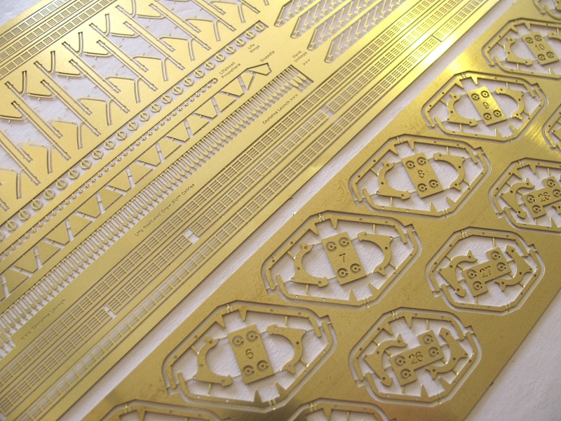
In order to create more than one Normandie model, all of the parts had to be reproducible. In the case of the photo-etched parts the individual frets could be duplicated once the original fret was found to be acceptable. However, the hull and detail components required silicon molds so the parts could be duplicated in resin.

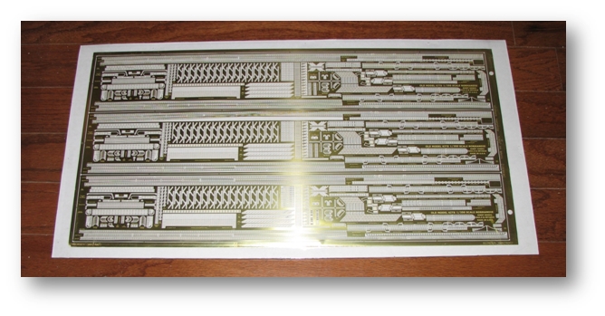
Original prototype PE frets for davits and small parts (click either to enlarge)
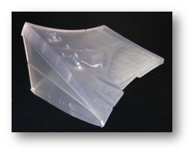
Making the Molds: The upper hull had to be assembled from four individual pieces and the lower hull from two. The parts had warped since printing, which meant an internal support structure had to be created to realign the parts.
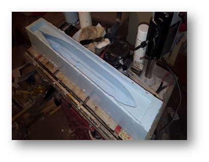
The original 3D printout of the main hull sections had an enclosed bottom to help maintain the alignment with the lower hull section. Leaving this material in place would make the hull a solid block of resin once the hull sections were joined, so it was removed when making the inner cores. The hull was glued to the core box and silicon poured to form the primary mold. After removing the bottom, clear packing tape was used to seal the portholes from the inside. The lower hull section(s) went through a similar process.


Joining hull halves and prepping for mold making (click either to enlarge)


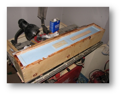


The creation of the first set of molds (click any to enlarge)
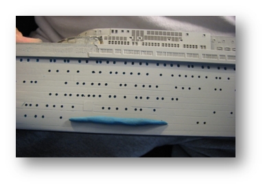
The first “pour” of resin showed promising results, but even the most shallow detail reliefs had bubbles of resin that were not part of the master hull. It was thought that the sunken details were too deep and air was being trapped during the pouring of the silicon rubber mold.

First casting showing flaws (click to enlarge)
The master hull ports and openings were modified by pressing clay into the openings, shaving the clay down to the hull surface, then countersinking with a handmade tool. This assured all the openings were set to the same depth. Both sides had to be done since “mirroring” reality has yet to be achieved.
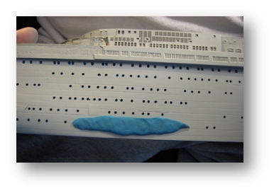
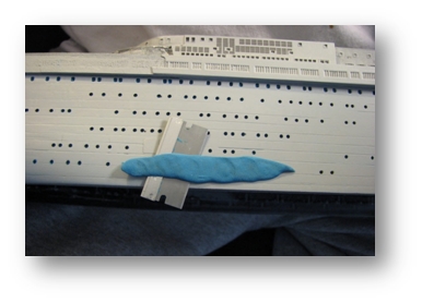

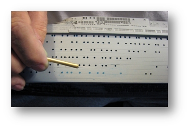

Manually filling all 600+ portholes and given them a defined depth (click any to enlarge)
There were 2 other potential sources for these bubbles: 1) the silicon rubber had been poured with no degassing, and 2) the resin was poured without pressurization.
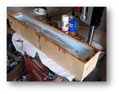
Once all the details had been reestablished, a new mold of the outer hull surfaces was poured. A vacuum chamber was not available, but the next pour would be pressurized. A “paint pot”, like those used for commercial painting, was lengthened 40″ to accommodate the full length of the hull mold. Resin was poured into the mold, the mold was slid into the pressure chamber, and a compressor raised the pressure to 60 PSIG.
Pressure chamber for molding the Normandie hull and small parts (click to enlarge)
The fixes that had been applied worked well, but an unexpected blemish ruined an otherwise usable casting. Without degassing the silicon before pouring, subsurface bubbles clung to undercut areas of the hull. When resin was poured, then pressurized, the thin membrane between the bubble and the model surface broke through. Although the bubbles could not be seen in the mold, pressurized resin would fill the bubble pocket and create “B-B’s” of resin on the surface of the casting.

Pressure casting flaws from air in the mold rubber (click to enlarge)
The master hull was used once again to make a completely new mold. This time the silicon was poured on smaller, degassed amounts with the aid of a vacuum chamber. The results were perfect.
Vacuum chamber used to ‘de-air’ the mold silicone (click to enlarge)
Finally – almost zero air bubbles in the resin and no protrusions (click to enlarge)

Even in its raw form, the Normandie is still a beautiful ship (click to enlarge)
Degassing the silicon, and pressurizing the resin had solved most of the problems encountered in previous pours. 14 upper and lower hull sections were created with 100% success (no rejects).
Building an example model was next, but first “how about some instructions?” A 58 page set of instructions was created that utilized virtual model and real life images to walk the modeler through the process of building the Normandie as she was originally configured; only this time in 1/350 scale.

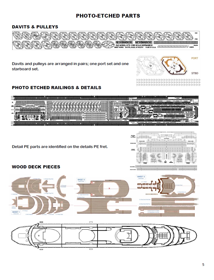


Kit instructions cover and sample pages (click any to enlarge)


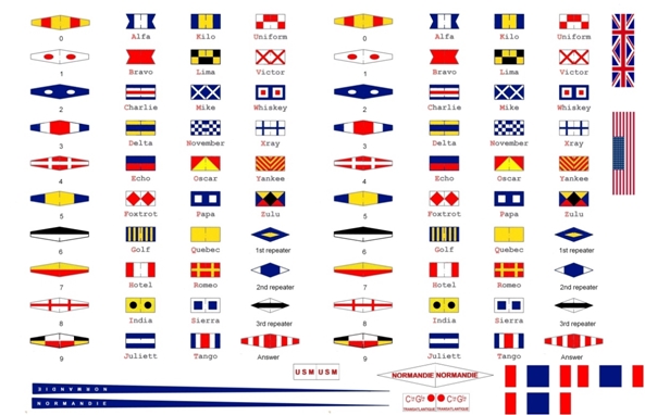


Wood decks, flags, decals and PE close-ups (click any to enlarge)
The Normandie Project had taken 9+ years to complete. More than 1/2 of that time had been spent acquiring accurate detail information and looking through and confirming resources. As the project progressed, new technologies were evolving that created changes in direction. However, those changes helped CAD software developers create more useful software (32 bit to 64 bit) and gave time for 3D printing companies to further develop their capabilities while wood decking companies created thinner more useful materials.
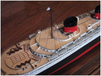
The finished model: The Normandie project was completed in June, 2016, including the building of the first model.
The first model, built from a production kit by Ken Friend
(click any to enlarge)


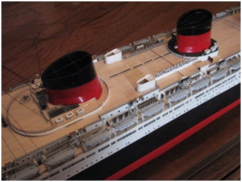


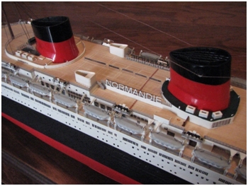

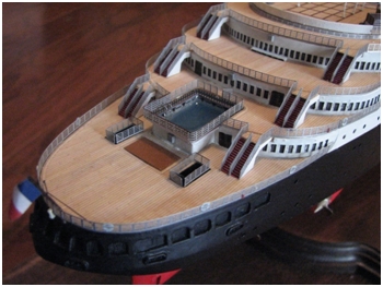
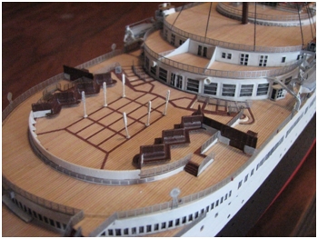


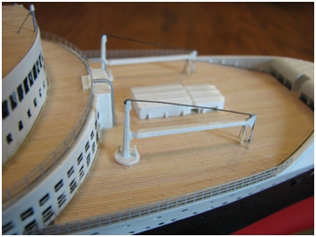
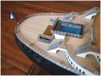
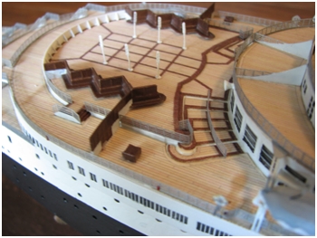
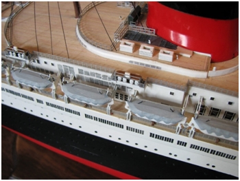
(click any to enlarge)
Alan: Of course we could go on almost indefinitely. In the end, every model is an engineering compromise and this one is no exception. We simply hope that it provides enjoyment to those who build and display it, and that they feel it is the most realistic and detailed model of the SS Normandie to date.