
By Frank Leimbek
BACKGROUND
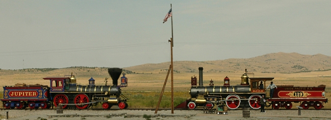
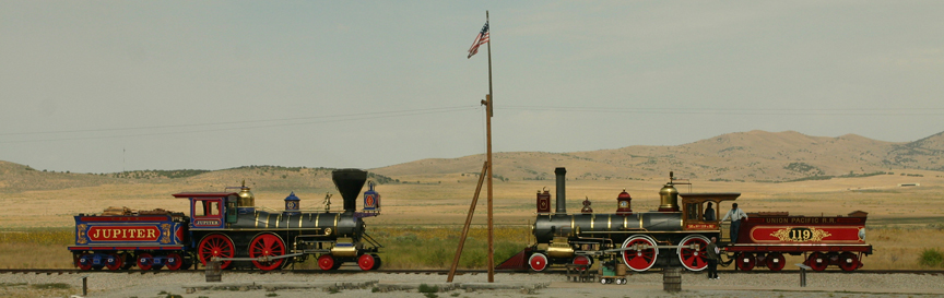
Two locomotives met at Promontory Summit on May 10, 1869, signaling the completion of the transcontinental railroad. This is now the Golden Spike National Historic Site located in Utah north of the Great Salt Lake. Replicas of the two engines meet there again during reenactments. The wide open spaces and the gently rolling hills make it a beautifully poignant location.
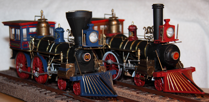
The completed models
When I saw a model of the General offered for sale on the Internet, I thought it might make a very cool model of the Golden Spike meeting. Of course I would need two models. I have a garden railroad in 1/29 scale and my father and grandfather worked for the Northern Pacific Railroad. I have specialized in 1/32 scale aircraft for many years. In other words, I like modeling and railroading so this was a great project.
Both locomotives are American type 4-4-0 engines. The No 119 was built by the Rogers Locomotive and Machine Works for the Union Pacific Railroad and burned coal. The Jupiter was built by the Schenectady Locomotive Works for the Central Pacific Railroad and burned wood. Its number was 60 but in those days some engines were also given names.
THE MODEL
The model used to construct the Jupiter and the No 119 was The General produced by MPC. The copyright date on the kit’s instructions is 1980. The kit was produced in bright red, brick red, steel gray, black, and gold colored plated parts. The main parts are emblazed on the reverse with ‘Made in USA.’ The scale of 1/25 promised a very nice size display. I purchased two kits from contacts I found on-line. Both kits were still factory sealed.
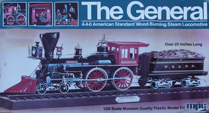
MPC The General Kit (click to enlarge)
The General was a pre-Civil War locomotive famous for the part it played in the famous James J. Andrews Raid at Big Shanty. Union forces commandeered the General and they were pursued by William Allen Fuller in the locomotive Texas. Many of the Union personnel on this raid were the first Medal of Honor recipients. This raid was the subject of several movies (The General starring Buster Keaton (1926) and later a Walt Disney movie). The wheel arrangement of this locomotive, known as 4-4-0, was the most popular road locomotive of the day. These machines were used on all railroads across the United States and were known as ‘American’ type locomotives.
The instructions for assembling these models were okay, with parts actually having labels (i.e. smokebox, pony axle, whistle control, etc.) However, the part numbering was very strange. For example, the left side of the pony truck (the set of front guide wheels) takes three parts. All have the same number. This might be a problem if the part numbers were easy to read. However, since the part numbers were stamped on the sprues, they were very small and only partly legible. Construction was performed by part shape identification alone.
The kit was not produced with very tight tolerances and almost every assembly required putty and/or sanding. The plastic has a very shiny surface that doesn’t yield a realistic looking model. Built ‘as is’would give you a cheap toy look. The ‘gold’ plated parts that should be brass on the real locomotives look particularly bad. I spray painted these parts with Rust-oleum Antique Brass Metallic (7274). It cut the shine and imparted a nice weathered look. The wheels are molded in red plastic and should be red but again I had to repaint in order to obtain a realistic appearance.
I used several glues depending upon the need for instant hold (Loctite Gel Control Super Glue) or seam and clamp application (Plastruct Plastic Weld). Work was slow since some parts needed to be worked, glued, clamped, and put aside until bonded before the next step could be started. The assembly usually needed filling and sanding. I used Plastic Putty by Vallejo for filling and smoothing joints. It worked very well.
Several changes needed to be made to the locomotives in order to model the Jupiter and No 119. These are detailed below.
TRACK
The kits came with a formed ballast and ties segment. I planned to put both together so that I could pose both locomotives facing each other. Both ends of the track segments are beveled. I cut the ends off one end of two sections so that they would fit together. I prepared the track segments by masking the ties and cutting out the masking between the ties.
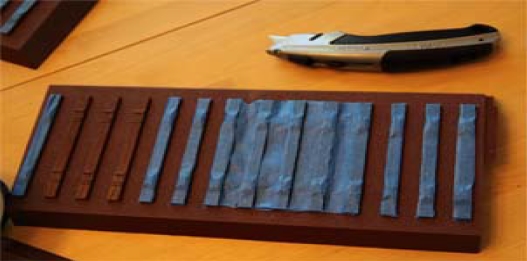
Figure 1 (click to enlarge)
I painted the rail segments with a stone look spray paint. When the paint was dry, I removed the masking tape from the ties (Figure 2). The next steps were to paint the ties (brown with streaks of black), rail retention plates and rail (rust), and glue the rails in place. The rails are molded in gray plastic. I painted them rust to match the retention plates on the ties.
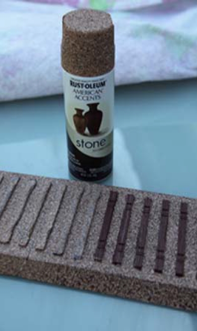
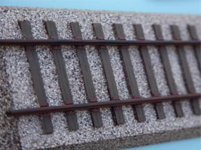
Figure 2 and Figure 3 (click to enlarge)
The application of a silver medium tip oil paint pen across the top of the rails was the finishing touch. I had a polished mainline rail look for the finished track segments (Figure 4).
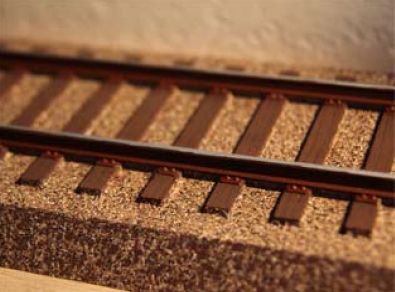
Figure 4 (click to enlarge)
TENDERS
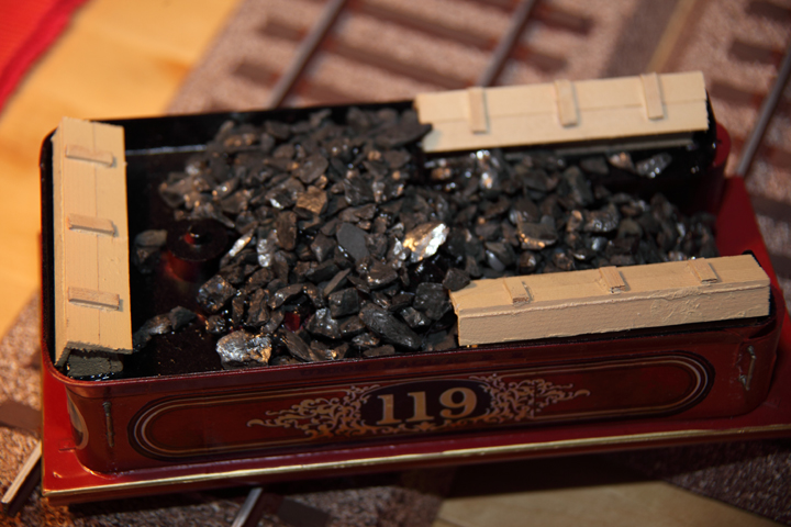
The tenders of both the Jupiter and No 119 are structurally the same. The Jupiter burned wood like the General. No 119 burned coal. Both of the real tenders had tool boxes mounted on the water tanks; however, the model did not come with tool boxes. I constructed the tool boxes using Canadian Red Cedar from Ozark Miniatures. I built two for the Jupiter and three for the No 119 (Figure 5). F or the Jupiter’s tender, I cut away the plastic wood load for tool box placement and painted the wood with light brown, tan, and black (Figure 6).
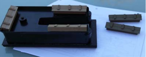
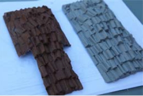
Figure 5 and Figure 6 (click to enlarge)
I filled the tender of the No 119 with model coal held in place with acrylic calking. If you need this type of bonding, note that the calking is white but dries clear. The Jupiter’s color theme is blue while the No 119’s is red. This color theme is carried through the tender and engine. The engine fenders, sand dome, headlight, and cowcatcher are the same color as the tender. Wheels are painted red. I painted the flange and wheel edges with the silver oil paint pen (Figure 7). This gave them the look of use as they rolled on the rail.
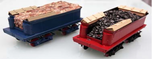
Figure 7
The last steps are to highlight edges with gold oil paint pen and add the custom decals.
LOCOMOTIVES
The model of the General had a molded place for a name plate on both sides of the engine boiler. I filed this off, glued a piece of plastic inside, and filled the hole with plastic putty. It took several applications with sanding to get the right curvature and look. In Figure 8 you can also see the ‘molded on’ boiler bands that should be brass bands to reinforce the boiler.
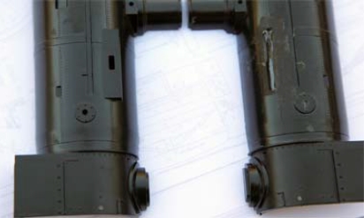
Figure 8
Since the Jupiter is a standard wood burning 4-4-0, it has a large spark arrestor around its smoke stack. The General had a raised section on the top rear of the arrestor and that had to be removed. Also the screen covering it was just molded plastic (Figure 9). I filed down the raised section so that the top was smooth and installed screen material to complete the spark arrestor (Figure 10).
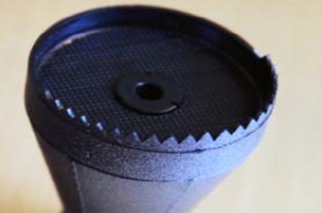
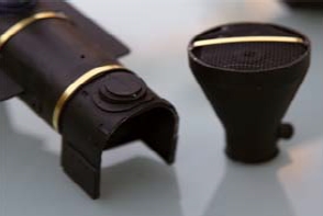
Figure 9 and Figure 10
The metal bands around the boiler were plastic details molded into the boiler halves. I sanded these off and installed brass flat bar from Special Shapes Co. (1/64 x 1/8). I drilled holes in the bottom of the boiler and also in the running boards along both sides. Wrapping the brass around the boiler, I inserted the bands into the bottom of the boiler. This was performed for both engines. Since both engines were from different manufacturers, they have slightly different band configurations. The number and location of the bands are different when you compare the Jupiter to the No 119.
No 119 was fueled by coal and therefore had a narrow, straight smoke stack. I constructed this from plastic wrapped around a Dramamine bottle. I wrapped two rings of heavy gauge braided wire around the top for detail. This engine’s smokebox was twice the length of the Jupiter’s smokebox. I re-engineered the smokebox front and extend the box with scrap plastic. I used plastic putty to smoothen the joint created by the addition (Figures 11 & 12).

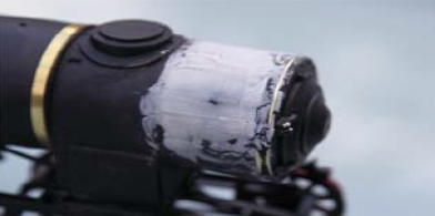
Figure 11 & Figure 12 (click to enlarge)
The driving wheels for the Jupiter were the same as the General. The counter weights were bolted into the wheels. This was represented with small bolts molded into the plastic. I painted the wheel set and they were ready for installation.
The driving wheels for No 119 had the counter weights welded into the wheels. I changed the kit supplied wheels to model the ones used on the No 119. I sanded off the bolts and added scrap plastic, filling the joints in with plastic putty. I sanded the joints.
The driving wheels of the No 119 were also red but had ‘white walls’ (Figure 13). I painted the wheel rims white with an oil paint pen. I painted the flanges and edges silver to represent wear. Paint pens come in handy for this type of work.
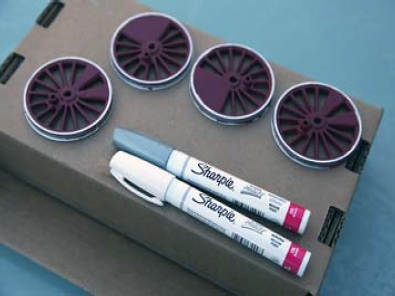
Figure 13
With the longer smokebox, the headlight was repositioned on No 119. The theme of red and blue was continued for fenders, sand dome, headlight, and cowcatcher. The completed engines look good after detailing the cowcatchers, headlight lens frame, and running boards with gold paint pens.
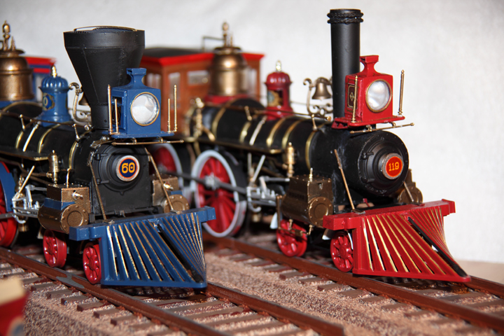
Figure 14 (click to enlarge)
Before World War I engine boiler jackets were made of ‘Russian iron.’ This was produced only in Russia by a special ‘pickling’ process which is now lost. This gave the boilers a polished look and was somewhat corrosion resistant. I painted the boilers with Future Floor Polish to give them a shine. The smokebox remained flat black.
DECALS
Great decals make the model. I did research on the Internet but I found all photos of very low DPI and totally unsuitable for use as decals in this scale. I took several photos in 2007 when I visited the national historic site. At that time I was not planning to build these models so I did not take complete photos. From what I did photograph, I was able to construct some fairly accurate facsimiles of the decoration (Figure 15 & 16). For example, using Photoshop, I used the Edit Distort function to take the side of a tender that was shot from an angle and correct it to a ‘straight on view’. I adjusted the size of all decals to achieve the proper look. Most of the decals are for the tenders. The others are for the engine cab, sand dome, and headlight.
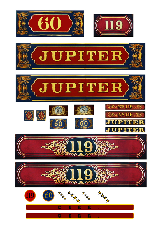
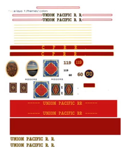
Figure 15 and Figure 16 (click to enlarge)
I experimented with various decal papers. I tried inkjet clear paper, but that showed too much of the underlying color. I used inkjet white paper. After printing I let it dry for a day. Be sure not to touch the paper and make sure it is clean. Any marks can screw up the result. After it was good and dry, I then sprayed it with Rust-oleum Gloss clear. I sprayed 3 light coats, letting the sheets dry completely between each. Like any spray painting, this should be done with plenty of ventilation. Some of the engine and tender color had a very slight darkening effect on the color of the decals. My source of paper was DecalPaper.Com. It released well and was easy to work into place. Setting solution also worked fine. I was very happy with the product. There was a slight problem with my first shipment and with an email they made it good without any extra charge.
Decals can also be made with ALPS printers that use a thermal wax-transfer process. The big difference is that these printers will print white. There are places on the Internet that offer those services.
COMPLETED MODELS
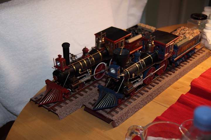
All the hard work was worth it.


The Jupiter and No 119 (click either to enlarge)
The Golden Spike Meeting (click to enlarge)
Other misc. photos (click to enlarge)