
Article and Photography by Ken Friend
Editors Note: It is my pleasure to bring you another article on modeling by Ken. Since Ken would never brag on himself, I must point out that his work has been featured in in FSM (Fine Scale Modeler) and he has won numerous awards in IPMS Competition. I know that I have learned an immeasurable amount from him and I hope you can too-Alan Bussie.
Some time ago I was asked to build a few models for display at the 2008 IPMS Nationals. The first of those was an Anigrand Mirage 4000, and while building the kit I thought back to the time when I built my first resin kit and of the changes in modeling techniques I had to adopt and/or develop. Other modelers I talk with are sometimes reluctant to build a resin kit, simply because they “don’t know what they don’t know” about building kits made of this different kind of plastic. I realized the Mirage would be a great beginner’s kit that could help new resin modelers get over their resin anxiety and open their collections to rare, one-of-a-kind, and unusual aircraft. First, a little history of just what the Mirage 4000 is all about:
HISTORY
The Mirage 4000 was a French prototype jet fighter aircraft developed by Dassault-Breguet from their Mirage 2000. The new aircraft was noticeably bigger and heavier, being fitted with two (SNECMA M53-2) turbofans, rather than the single engine found on the Mirage 2000. It also featured small canards above the engine air intakes. Despite the changes the two aircraft remain similar, sharing the delta wing design, semi-circular air intakes and general configuration.
The plane first flew in 1979. It was financed as a private venture by Dassault, possibly with Saudi Arabian money. The Mirage 4000 was comparable in size to the United States F-15 Eagle, and would have made an excellent long-range interceptor. Its weight and ordnance capacity also would have made it a very good fighter-bomber.
In the early 1980s Dassault ended the program shortly after the Saudis chose the F-15C as their preferred aircraft. The French Air Force preferred to concentrate on the Mirage 2000, leaving Dassault with no customers. Some of the expertise thus gained would later influence the Dassault Rafale, but the only prototype moved to its final residence at the
Crew: 1
Length: 18.70 m (61 ft 4 in)
Wingspan: 12.00 m (39 ft 4 in)
Height: 5.80 m (19 ft 0 in)
Wing area: 73.0 m² (785 ft²)
Empty weight: 13,000 kg (29,000 lb)
Power plant: 2× SNECMA M53-2 afterburning turbofans, 83 kN (19,000 lbf) each
Maximum speed: 2,445 km/h (1,320 kts, 1,519 mph)
Range: 2,000 km (1,100 NM, 1,200 mi)
Service ceiling 20,000 m (66,000 ft)
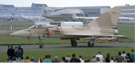
Figure 1: Mirage 4000 in Camouflage Paint Scheme
THE KIT
Resin kits have matured in accuracy, detail, fit, and finish and the end results are great-looking models of some of the rarest of aircraft. Resin kits build differently than injection-molded kits and sometimes unexpected problems arise. For example, a modeler might have to use a little extra filler for an errant bubble or two in some of the parts. No, you didn’t get the one and only kit with bubbles; it is simply a common side-effect of the molding process. Another change the resin modeler will encounter is the use of CA glues instead of the standard plastic cements.
Resin kits are manufactured with “short-run” tooling instead of expensive CNC and EDM machined hard metal molds. The reason for this type of tooling is simple – low volume. Therefore, short-run tooling is usually dedicated to the recreation of hard to find miniature models. In most cases, there is not an injection-molded equivalent. This provides a great opportunity for the modeler who just has to have a model of “that” plane. The end result of the resin experience and building that one-of-a-kind airplane can be even more rewarding than many injection molded kits.
The Anigrand 1/72 Mirage 4000 is typical of other resin kits I have built. First of all, you get a tiny box and a “bag” of parts in lieu of several part “trees”. A small, compartmentalized tackle box is really useful for keeping the smaller parts once they’ve been taken from the bag(s).
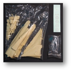
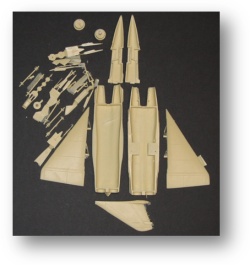
Figure 2: Resin parts seldom come on “trees”
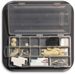
Figure 4: A small tackle box with dividers helps organize the small parts
Resin kits typically have fewer parts that their injection molded counterparts; instructions are more of an “exploded” view rather than step-by-step. (click on either image for a larger picture)


CONSTRUCTION
Extra time is usually required for the trimming of flash from each piece and the test fitting the individual parts. Resin kits often have “vents” on the parts that are required in the molding process
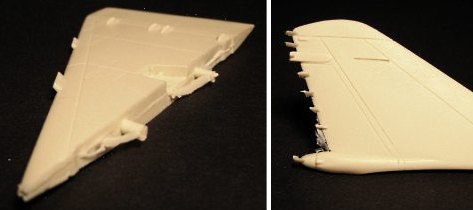
Figure 6: The Mirage 4000’s wing/fuselage mating Figure 7: The extra ‘teeth’ on the left of the stabilizer
surfaces required the removal of gating and flash were probably used to ensure correct fill-out during mold
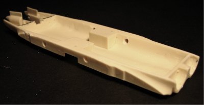
Figure 8: The fuselage pilot holes for the wings were re-drilled for size and location
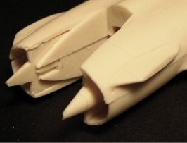
Figure 9: The intakes of the Mirage look simple, but are complex to recreate.
The thin lips on the outside of each one aligned almost perfectly and required only minor touch-up
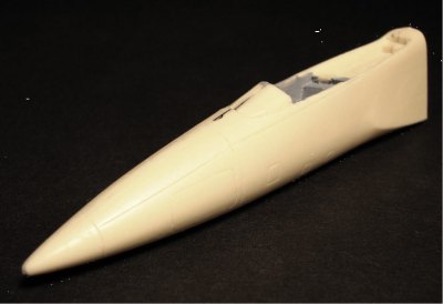
Figure 10: The mating of adjoining pieces in a kit is critical if detail is to be maintained
Various aspects of a resin kit build can benefit from the use of a variety of CA glue types. “Fast” CA is best where parts need to go together quickly. “Medium” CA can be used when parts need to be aligned after the glue has been applied. “Gap-filling” CA comes in handy for a multitude of repairs. Before applying any glue, all parts should be thoroughly washed in warm soapy water, rinsed, and dried. This process will also assure that paint will bond properly and not “fish-eye”.
In the early days of resin kits part alignment wasn’t as good as it is today. Misalignment discouraged modelers from pursuing this type of kit simply because re-alignment took so much time and effort. The Mirage 4000 parts line up well with one another even at the test fitting stage. Getting the mating parts to match up is difficult enough to accomplish in an injection molded kit, let alone in a resin kit; kudos to Anigrand for getting this part right and saving us all a lot of extra work.
The intake pieces on the Mirage 4000 went together well after a good trimming and some minor sanding. The small imperfections shown in the pictures required a little more touch-up than they would have in an injection molded kit. Here is where clean parts are essential. Neither of the inlet spikes in my kit had filled out to a point. Until I thoroughly cleaned the area, filler wouldn’t even stick; one touch with sand paper, and it was gone. I actually enlarged the incomplete area before I applied the next coat of filler. Cleaning and roughing the area created a good bond.
The alignment of the upper and lower fuselage halves was also good, while the alignment of the wings on the fuselage required adjustment. The pegs on each wing were sanded undersize so I could adjust them just a little to get the surfaces to line up. A step by the ailerons in the main mating surfaces was moved aft with a little grinding.
Overall, I was pleased with the fit and finish of the parts, and found the additional work required to eliminate blemishes within reason. Figures 12, 13, & 14 show the preliminary adjusted fits:

Figure 11: The inlets after clean up
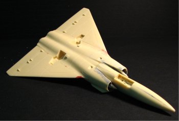
Figure 12: The underside didn’t require a whole lot of work
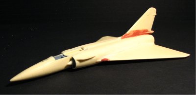
Figure 13: The basic contours take shape
This is where I had to make a decision. As an Aviation Metalsmith in the Navy, I learned to appreciate the manufacturing aspects of the aviation industry. As a modeler I have always been dismayed at the unrealistic portrayal of panel and rivet lines, especially in 1/72 scale. Kit panel lines often represent gaps between panels that would be as much as 1” on the real aircraft. This occurs in almost all kits, regardless of the method of manufacture. A person doesn’t typically think of sheet metal work as “precision” when compared to machine shop fabrication. However, the gaps between exterior panels on military aircraft rarely exceed 0.030”, and that only occurs around patched areas. That means in 1/72 scale the panel gaps would be just over 0.0004”, barely visible to the naked eye.
I looked closely at the panel lines of the real Mirage 4000 on the Internet. There were 2 different paint schemes; all white with blue and red markings (demo version), and camouflage. Some pictures of the all white version show panel seams simply because the plane is dirty. In other pictures the panel lines are just barely visible. Amazing what a little soap and water will do. Pictures of the camouflage version seldom show panel lines, even when dirty.
I decided to build the “clean” camouflage version and wanted the panel lines to be softer and less eye-catching. So I filled all of them with automotive glazing putty except the lines that indicated moveable control surfaces. After sanding, the lines were just slightly deeper than the surface of the wing/body, and much more realistic.
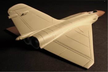
Figure 14: Bringing panel lines into scale was necessary
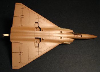
Figure 15: The underside panel lines weren’t as wide as those on the upper fuselage
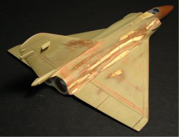
Figure 16: The top panel lines after filling
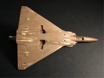
Figure 17: The underside panel lines after filling
Personally, I am not a big fan of vacuum-formed canopies. But, here again, Anigrand makes good vacuum-formed canopies with ample trim lines that fit the model well after trimming to those lines. I gave up using scissors and/or an X-Acto knife on this type of canopy a long time ago after ruining too many in other kits. The best tool I have found so far is a sanding drum mounted on my Dremel. When run at a moderate speed, material removal is quick enough to keep from getting bored and yet fine enough to get straight, clean edges. You only have one shot at getting it right. However, if you do require a new one, you can usually get a replacement from the vendor. It is better to make the first cut about 1/32” outside the guide lines, test the fit, and finish accordingly.
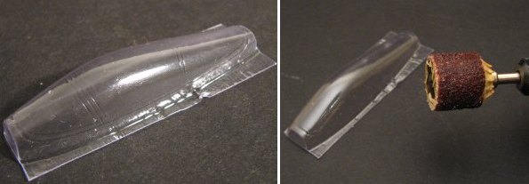
even the best modelers will trim vacuform material accurately and quickly
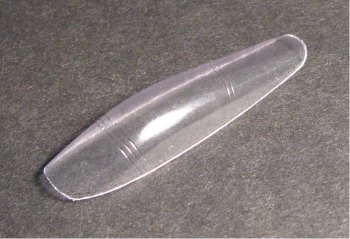
Figure 20: Phew! I didn’t mess it up!
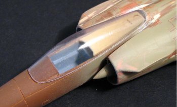
Figure 21: The trimmed canopy matched fuselage contours well
PAINT & DECALS
The finish of a model is a direct reflection of the quality of the work that went into the model prior to the application of the final finish. Paint and/or foils will show any flaw that was missed during the build process. Painting may require light sanding and more than one coat to eliminate small blemishes. Foiling might require the stripping of one whole piece of foil to remove an errant cat hair or two.
Just a word of caution here: I have spent many agonizing hours applying, then stripping, a wide variety of foils and foil adhesives from resin models. The foiling of a resdin model requires a super clean surface and genuine foiling adhesives. The resin material itself will expand and contract in sunlight and shade. Thin foils will bubble whereas thicker foils will resist deformation. Foiling in smaller panels will help reduce the problems as well. However, every effort should be made to keep a foiled resin model at constant temperature. Taking a foiled resin model from and air-conditioned room into a bright summer’s sun for photography is fine until you return to the air-conditioning. Once the resin starts to contract, its bubble-mania. Shipping these models will have the same effect.
Resin is more porous than injection molded plastic, so it might take longer to dry after washing. Once the surface is clean and dry, acrylics and enamels will adhere well. For the Mirage, I used Model Master “Acryl” paint for main paint scheme and Model Master buffing and non-buffing Metalizing Lacquer for exposed metal parts. The camouflage paint scheme on the Mirage 4000 presents some unique challenges. For example, the light gray underside has a sharp edge where it meets with the camouflage of the upper fuselage. If this blend line was “feathered” it would be easier to shoot from the underside. However, the crisp line requires masking to get the sharp change. This is a good place to use “safe release” masking tape that won’t damage the existing paint.
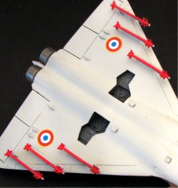
I elected to paint the underside of the model first and then mask for the camouflage upper fuselage. This required the addition of the missile pylons and other pieces that would also be gray.
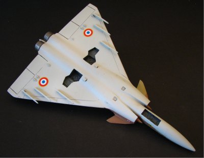
Figure 22: Before painting, all pylons and other pertinent hardware should be added
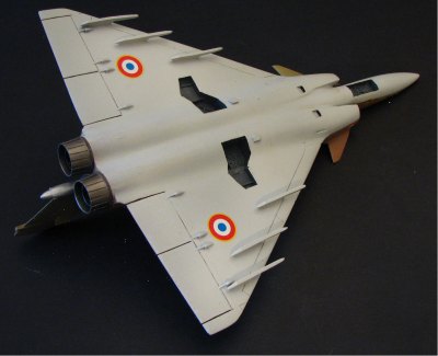
Figure 23: The gray underside didn’t require masking at this point
After masking the horizontal blend line, the upper fuselage was first air-brushed with the lighter sand color of the camouflage. The camouflage pattern was then masked with liquid masker and the darker earth color applied. Once the liquid masker was removed, the whole surface was wet sanded with 600 grit wet-or-dry until the edges were smooth to the touch. Touch-up was done on both colors with a broad, soft, nearly dry brush. Decals were applied with Microscale “Micro Sol” decal-setting solution and then the whole plane was air-brushed with a flat overcoat.
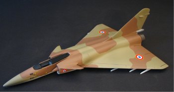
Figure 24: Using a wide, soft, nearly dry brush for touch-ups will help to minimize or eliminate brush marks
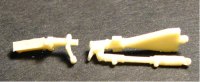
Until this point in the build, all the parts were large enough to absorb a lot of bumping, cutting, filing, sanding, and otherwise abusive treatment. Now came the most tedious part of the build; the small parts. Small resin parts sometimes do not fill out completely, get broken in shipment, or are somewhat misshaped. This is an accepted part of the resin kit world. The 6 missiles cleaned up well after trimming flash, filling blemishes, and straightening.
The nose gear in my kit was broken in two. The pilot holes in the wheels required drilling. The pegs on the landing gear in this kit are ample enough to provide good alignment of the wheels. Some modelers elect use suitable landing gear from injection molded kits to replace the resin versions simply because the resin pieces are so fragile.
underside stand out dramatically. Any flaws Modelers sometimes use similar parts
here would detract from the model from injection-molded kits
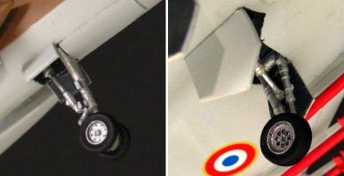
Figure 27: The landing gear in this kit has good detail after cleanup
There usually isn’t a lot of cockpit detail in 1/72 resin kits, and what is there requires being able to write ones name on a grain of rice to highlight the raised features. It’s a wonder there is any detail at all in some 1/72 scale models.
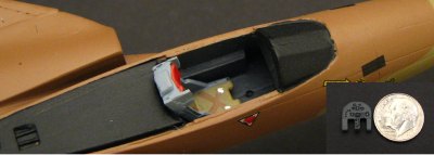
Figure 28: 1/72 interior detail is sparse and tiny. Inset: a US Dime shows the size of the instrument panel.
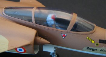
Figure 29
Figure 29: Allowing the Model Master Canopy Glue to set slightly before putting the canopy in place will help keep the glue from wicking up the side surfaces of the canopy. Although the canopy trimmed out well, final blending was necessary once the canopy glue set. Filler must be applied cautiously; this is where the flat overcoat helps prevent damage to the paint scheme and decals. The blending process requires very light sanding with no more than 600 grit wet-or-dry, and usually requires more than one application of filler.
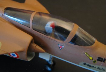
Figure 30: Front and back windscreens are permanently attached to the fuselage, so only the center sliding portion has a panel line
I saved the pitot tube until last simply because I knew it would be broken off several times if I put it on early in the build. In this kit the piece is so small that I originally thought it was a piece of flash. The probe had somehow acquired a 1/8” bow to it over its ½” length. Resin doesn’t bend well without breaking, but somehow, I was able to massage it enough to get it straight. I then sanded a flat on the nose of the plane and a flat on the mating surface of the probe. Using medium CA to attach the probe I then hung the plane in nose-down position so I could maintain the alignment while the CA cured.
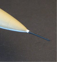
Figure 31: The pitot tube should be the last piece added
since it is usually the first piece broken off during assembly
Figures 32-35: Mirage aircraft are beautiful from any angle. The Anigrand Mirage 4000 can be a great addition to a collection of rare airplanes
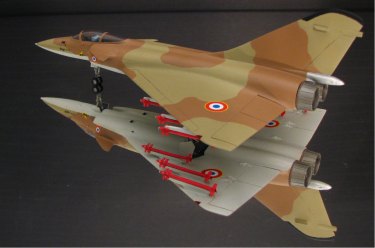
Figure 32
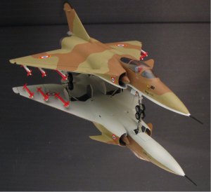
Figure 33
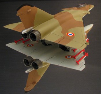
Figure 34

Figure 35
CONCLUSION
It is difficult to dispute the aesthetic virtues of the Mirage aircraft. It is simply an elegant design that is fun to model and looks great in any collection. Anigrand’s 1/72 Mirage 4000 is no exception. Detail parts in 1/72 scale present difficulties for even the best resin kit manufacturers. I compliment the manufacturers of these kits on their ability to generate models that would otherwise be unavailable. The fit and finish of resin kits has improved so dramatically that modelers at all skill levels should take a second look. The Mirage 4000 is a wonderful kit that experienced modelers will enjoy and first-time resin kit modelers can use to gain new modeling experience.
I have enjoyed building resin kits and will continue to do so as long as my wife will let me. If you are a first time resin kit builder, be prepared to change your modeling thought process a little. You will eventually overcome any differences and take them in stride. Once you’ve acquired these new skills, I think you will also find you do better work on all your models, regardless of whether they are “poured” or injection-molded.
REFERENCES
• Wikipedia, the free encyclopedia
MATERIALS
• Model Master “Acryl” paint for main paint scheme
• Model Master buffing and non-buffing Metalizing Lacquer for exposed metal parts
• HobbyTown super thin, extra thick, and gap-filling CA glue
• Model Master Clear Parts Cement and Window Maker
• Microscale “Micro Sol” decal-setting solution
• 600 grit wet-or-dry sandpaper
kfriend@frontiernet.net