
By Fred Boucher
with kit history by Alan Bussie
Introduction
In the salad days of the early atomic and jet ages, Cold War fears pushed the envelope of aerospace design and an atomic powered strategic bomber was seriously considered. Convair, Lockheed and Northrop (perhaps others) submitted proposals for such a plane and reactor-fuel concept engines were built. And if a nuclear powered jet bomber isn’t growling-Geiger counter-cool enough for you, consider the zany nuclear powered Mach III SLAM (Supersonic Low-Altitude Missile) of Project Pluto† streaking just above the tree tops, spewing radioactive particles in its wake and lobbing H-bombs. Brigadier General Jack D. Ripper’s dream come true!
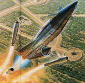

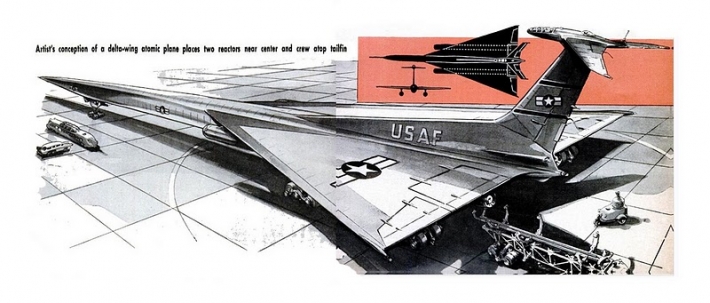

SLAM (Project Pluto), three popular Atomic Bomber concepts and the nuclear turbojet engine (click any to enlarge)
USAF was not the only air force to explore an aerial nuke plant- the Soviets did, too. And Hawk was not the only model company to kit a fanciful model of that radiant subject. Aurora kited the Russian Nuclear Powered Bomber shown below and also reviewed on this website.

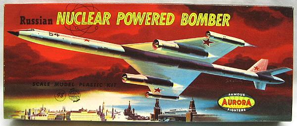
The original magazine article and the resulting Aurora Kit (click any to enlarge)
Your humble reviewer built this marvellous model aeons ago – I still have the parasite fighters from it! It was, in the lexicon of the era, one cool kit!
“hawk” or “Hawk”?
OK, was it hawk or Hawk? Their logo was ‘always’ spelled in lowercase. Yet the company name as printed on the instruction sheet is capitalized. While I personally want to use hawk, henceforth I will punctuate it as a proper name: “Hawk.”
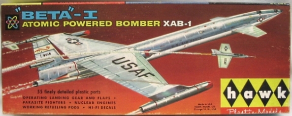
Kit History
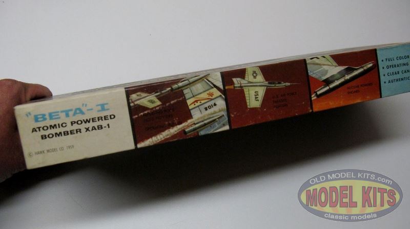
Hawk, like Aurora, liked to be first to put new concepts into a kit. Combining Atomic Power and the parasite fighters, Hawk issued this kit in 1959, shortly after conceptual drawings of Nuclear Powered Bombers appeared in popular magazines. The first issue was in a sturdy hardbox (a thick cardboard upper box lid and tray, with the top covered with a lithographed paper ‘slick) and was given part number 514-98. This exact artwork layout was used in the second issue (roughly 1961) with no changes other than the part number. It was changed to 514-100.
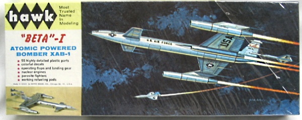
The third issue was dated 1964 and sported completely new art. This time, Hawk went to the ‘softbox,’ a thinner cardboard with no slick – the printing was directly on the box lid. There were no changes inside and the clear, red-tinted translucent ‘flames’ were still included. Around 1966 there was another issue, but the only change was the kit number to 514-130. This was to be the final issue of the Beta 1. The final year of issue is not known but was probably in the late 1960s.
In The Box
Hawk packed this issue with imaginative box art showing an XAB-1 “pulling cons” as it fissions it’s way skyward, one of the parasite fighters breaking away to serve and protect. Inside the box were instructions, decals and sprues holding 55 injection molded parts of silver, clear, and translucent orange.
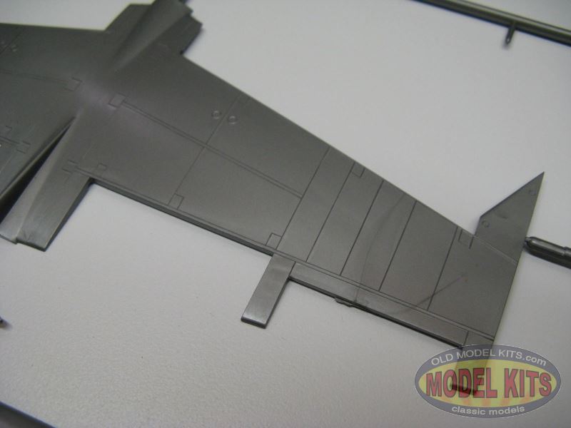
Examine the photographs; Hawk’s molding was good with crisp edges, minimal flash, no noticeable sink marks, minor mold seams, but with visible ejector circles. The pieces had a smooth surface texture although Hawk molded them thick with stout sprue tree attachments.

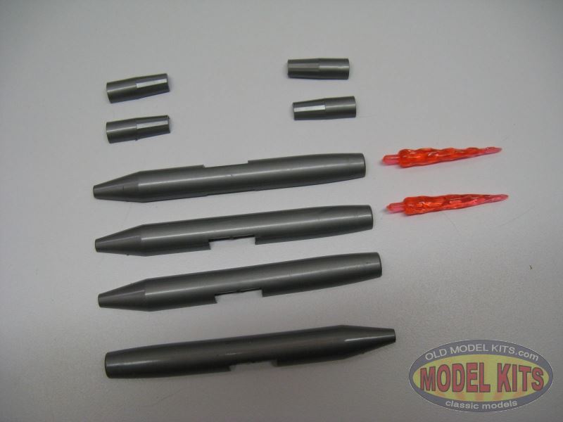

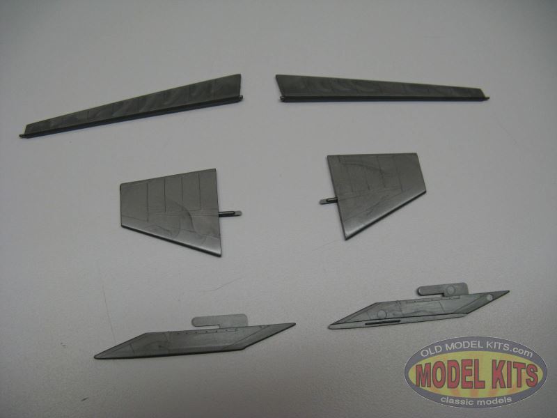
Bomber parts overview (click any to enlarge)
Back in that era many modelers wanted ‘action’ features and Hawk gave the people what they wanted. The XAB-1 features moving control surfaces, retractable landing gear and detachable reactor nacelles and parasite fighters. The box heralds “…working refueling pods” although I can’t find anything in the assembly instructions nor on the sprues about refueling pods. Perhaps they are the detachable reactor nacelles?
‘Action Features’ (click to enlarge)
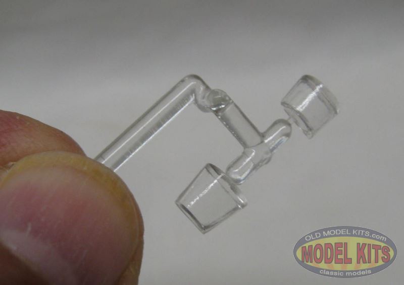
Some concept designs show a much different canopy arrangement than this model sports. You decide which is accurate.
Scale
We can consider this kit as “box scale” although Hawk mentions it as 1/188. “Box scale” was whatever size resulted from the model company scaling the kit to fit inside their zillion boxes bought at bulk price. Back in the day the nascent plastic modeling hobby was less discerning about matching subjects accurately to scale. Those boxes were (are) easy to stack!
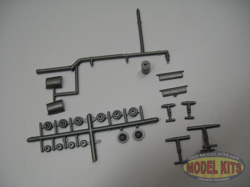
Detail
Not much. Relatively thick raised panel lines and access hatches detail the exterior. The only rivets I see are along the top of the nacelle pylons. The landing gear legs are just poles of plastic and the wheels are just doughnuts of styrene.

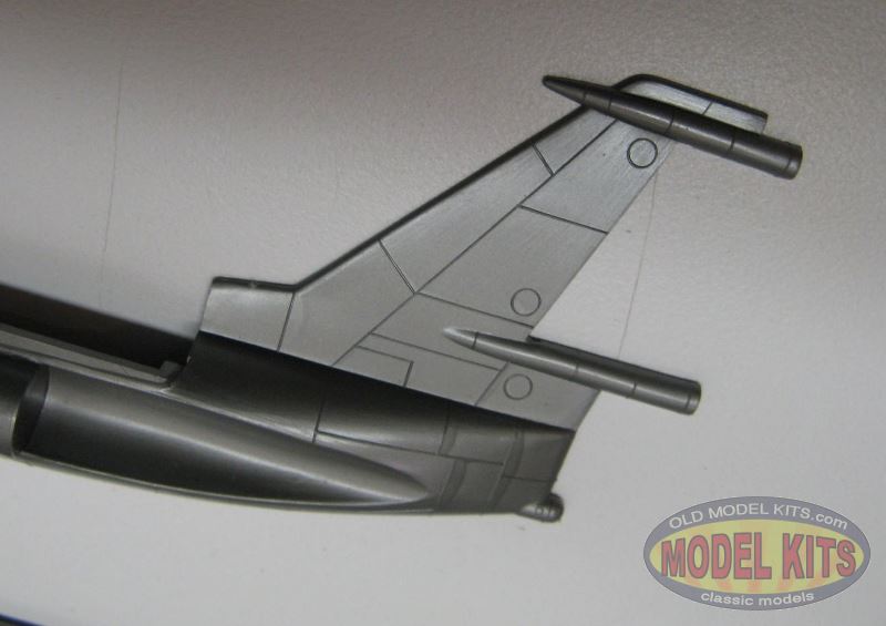


Parts close-ups (click any to enlarge)
I guess that the working features are the details. Gear doors snap into place and can be closed when the gear is retracted. Another detail is the pair of “flames” – nice plumes of radioactive afterburning propulsion, simulated with the translucent orange exhaust plumes.
The little fighters are one piece each. They resemble nothing I have ever seen.

Decals, Instructions and Painting
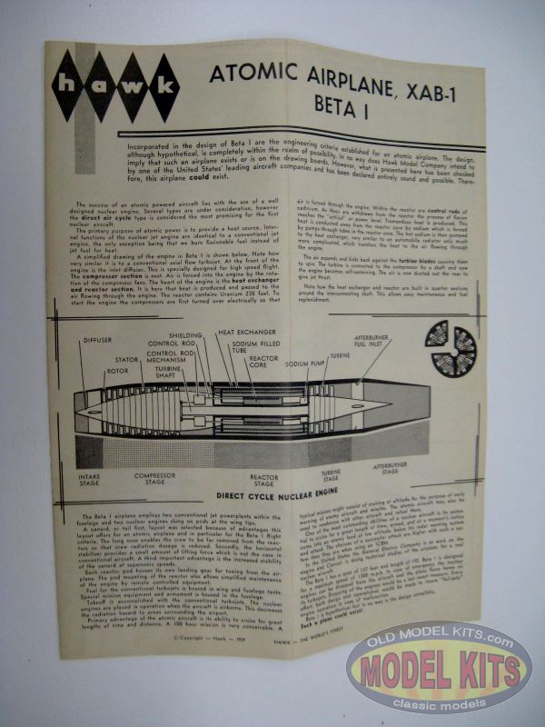
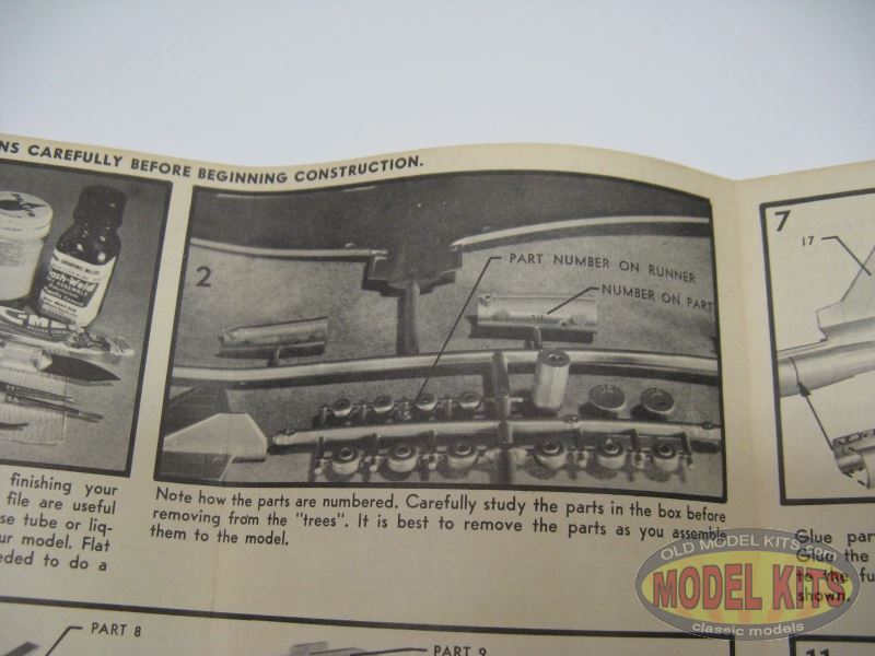
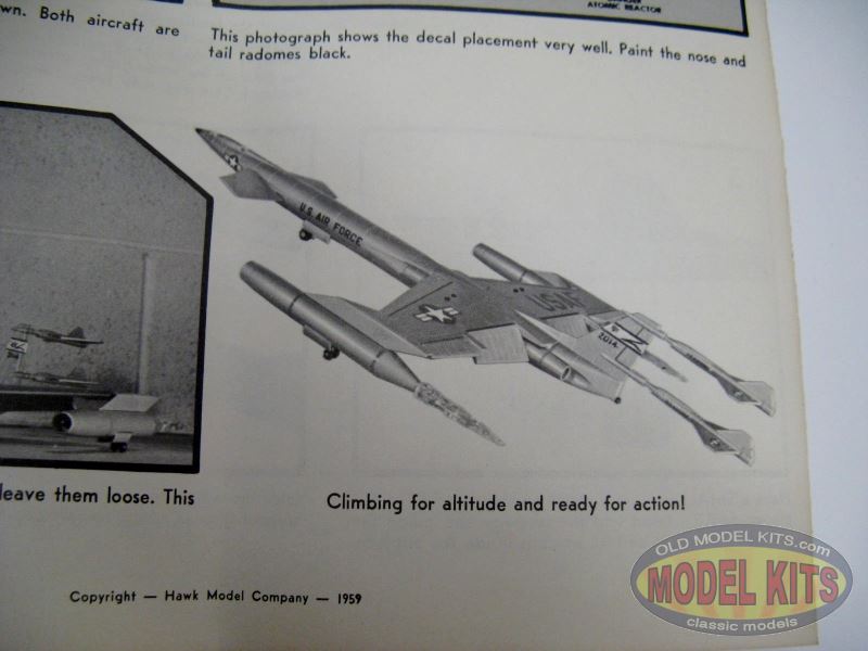
Hawk produced a simple yet nicely printed and presented instruction sheet. The front page presents a history of the aircraft and includes a keyed illustration of a Direct Cycle Nuclear Turbojet. Eighteen steps, illustrated with photographs, guide the modeler through construction. The first two images show the suggested tools and paints, plus how the parts are labeled on the part trees. The back cover shows the completed model on the ground, as well as climbing for altitude and ready for action! The former photograph would look better if it had not been shot in front of a cinder block wall. Classy marketing, “hawk”!


(Click any to enlarge)
Painting is minimal, requiring only a few colors. No paint brand was recommended, although Pactra bottles (intended or not) are shown in the tools image.
The decals sheet is fairly comprehensive, with many USAF and national insignias for the bomber and the two fighters. Red rescue triangles, service stripes and servicing circles are included. Only one bomber is represented, number 2014. The decals are opaque, sharp, and mostly well registered. However, there is more excess carrier film than accepted today. I’d like to try to bleach them in the sun and see if they would hold together in water. If you have this model and want to try the decals, I suggest you read the two articles about saving or restoring old decals at OldModelKits’ website.

Beta Decals (click to enlarge)
Conclusion
“Beta”-I glowed with the energy of imagination back in those chilling times. A fanciful kit, it offers some interesting features. Some modelers may find the orange exhaust plumes as hokie, yet I like them.
Drawbacks are thick parts, molding blemishes and simplistic detail.
All the same, I really enjoyed this model when I built it as a kid, so much so that I kept the little fighters after the bomber was relegated to that great model boneyard in the backyard. If I can find another one of these, I plan to build it!
Nuclear aircraft engines
In pursuit of what atomic energy might offer the United States Air Forces, in 1944 a program was initiated to produce an operational nuclear powered bomber.
The principles of atomic aircraft propulsion were explored early in the atomic age. As early as 1942 Enrico Fermi and his associates involved with the Manhattan District Project discussed the use of atomic power to propel aircraft. After WWII, in the developing cold war political climate, the idea of a nuclear armed and propelled bomber that could measure it’s patrol times in weeks rather hours was extremely attractive to the US military.
In May 1946, the Air Force began the Nuclear Energy for the Propulsion of Aircraft (NEPA) project which was followed in May 1951 by the Aircraft Nuclear Propulsion (ANP) program. While the NEPA project was mainly concerned with research, the ANP program had the ambitious goal to turn this research into a working prototype. Two different systems were pursued, the Direct Air Cycle, and the Indirect Air Cycle.
The Direct Air Cycle concept was assigned to General Electric based at Evendale, Ohio. This system had advantages in cost, simplicity and reliability. Conventional jet engine compressor and turbine sections were used, with the compressed air run through the reactor itself to heat it before being exhausted through the turbine. This configuration had the additional benefit that the aircraft could take off using on chemical power, then switch to nuclear once the core reached operational temperatures, reducing deployment time.
HTRE-1
A series of tests were run known as the Heat Transfer Reactor Experiment (HTRE), involving three different reactors, with the purpose of determining the most efficient method. This program produced the successful X-39 engine, which consisted of two modified General Electric J47s turbojets, with heat supplied by the Heat Transfer Reactor Experiment 3 (HTRE-3).
Development of the Indirect Air Cycle was assigned to Pratt & Whitney. In this configuration, the air did not go through the reactor core, but instead was passed through a heat exchanger. The heat would then be carried by liquid metal or highly pressurized water to the turbines where the hot air would drive the aircraft. Being a closed system, this concept would have produced far less external radioactive pollution. While progress was made, by the end of the ANP project, Pratt & Whitney failed to produce a workable system.
After establishing the parameters for the power plant and the transfer mechanism, engineers commenced work on the difficult issue of shielding for the crew and avionics systems. Initial plans proposed shielding the reactor with massive layers of cadmium, paraffin wax, beryllium oxide and steel. The idea being that the more protection the reactor had, the less shielding the crew cabin would require.
In theory this approach was workable. However in the context of aircraft design, weight or rather that lack of it is all important and this design was rejected. It was decided that the best approach was to use a concept known as “shadow shielding”. The layers of protection would be equally divided between the reactor and the crew cabin (also referred to as the divided shield concept). The crew being in the ‘shadow’ created by the shields. This system satisfied weight requirements, but meant that both the aircraft and the ground staff and equipment were exposed the significantly higher levels of radiation.
One unverified proposal for the problem of shielding was to use only elderly air crew. The reasoning being that the effects of radiation injury and potential sterilisation were of less significance to crew and pilots over a certain age.
Shielded Cockpit
Having tackled the reactor, transfer mechanism and shielding problems, the program moved it to the aircraft design stage. The only proven airframe large enough was the Convair’s B-36 Peacekeeper Bomber. The Peacemaker had entered front line service with the U.S. Air Force in late 1948 and was the Strategic Air Command (SAC) main nuclear deterrent platform. The B-36 was truly massive, with dimensions impressive even by today’s standards. It had a 70 meter wingspan, was 50 meters long and had an incredible take-off weight of 186 metric tons, making it the only feasible contender for the role.
The original crew and avionics cabin was replaced by a massive 11 ton structure lined with lead and rubber. Additionally a 1-foot-thick (30 cm) leaded glass windshield was used, and water tanks were placed in the aft section to help absorb any stray radiation. The other section of the plane that underwent significant modification was the rear bomb bay. Much of the internal structure was removed in order to make space for the nuclear power plant. With these alterations in place, the aircraft received it’s new designation of NTA (Nuclear Test Aircraft) or XB-36 (and later NB-36H).
The tail plane was marked with a radioactivity symbol, and an “R1” denoting the one megawatt of power it’s reactor would generate. The 16,000 kg liquid-sodium cooled power plant would be winched into the plane’s bomb bay every time the NB-36 was scheduled to take to the air. When it landed, the reactor was removed again for safety reasons and to facilitate research into reactor performance.
Between 1955 and 1957, the NB-36H completed 47 test flights and 215 hours of flight time, during 89 of which the reactor was critical. The reactor was operational but did not power the aircraft, its sole purpose was to investigate the effect of radiation on aircraft systems.
It was concluded that using a nuclear power plant to provide an aircraft with virtually unlimited operational range was indeed possible. Impressive as the NB-36 was, the concept of a nuclear powered aircraft was rendered irrelevant by the development of the ICBM as a nuclear weapon delivery platform. Additionally public concern about the dangers of flying a nuclear reactor over their homeland made the concept politically undesirable. In the end, after expending in excess a billion dollars on the program and having developed a working prototype, the U.S. Air Force shelved the program in the late 1960s.
It should be noted that the United States was not the only country to produce an atomic aircraft. In the 1960s, the Soviet Union‘s Tupolev design bureau conducted a similar experiment using a modified Tu-95 bomber known as the Tu-119. In fact rumors of a Soviet project may have partially motivated the Americans in an attempt to close a potential “nuclear bomber gap”. *
************
This is a rather unique case of where an extremely substantial hangar was built, but never the accompanying runway!
The National Reactor Testing Station (known today as the Idaho National Engineering & Environmental Laboratory) was established in 1949 in a very remote part of Idaho. Test Area North was constructed in the early 1950s at the north end of the NRTS property, about 27 miles northeast of the Central Facilities Area.
It was built by the USAF & the Atomic Energy Commission to support the Aircraft Nuclear Propulsion Program, an attempt to develop a nuclear propelled bomber. Beginning in 1955, TAN was the site of the Heat Transfer Reactor Experiments (HTRE), which conducted ground-based testing of what was intended to be the prototype aircraft nuclear engine.
The aircraft which was intended to use this powerplant was the Convair X-6.
The X-6 was orioriginally intended to be based on Convair’s B-36 bomber, but the design was later changed to use Convair’s B-60 (the swept-wing development of the B-36) as its baseline.
The X-6 was intended to have conducted its flights from Test Area North. A huge (350′ wide) hangar to house the X-6 was constructed at Test Area North,built with enormously thick, nuclear-shielded walls & bays.
General Electric, the program contractor, planned to equip the engine maintenance facilities with closed-circuit television systems and remote manipulator arms to allow technicians to work on the aircraft & its powerplant without direct exposure to the intense radiation field that would persist even after the reactor was shut down.
Since the turbojets essentially functioned as the cooling system for the reactor, they would have to be run at high power settings even after shutdown of the reactor in order to maintain cooling airflow through the still-hot core.
After an initial cool down period, ground cooling systems would be connected to the reactor and the engines could be shut down as the reactor was extracted from the airplane & placed in its shielded storage bay.
It was estimated that the tremendous weight of a nuclear propelled X-6 would have necessitated a 15,000′ runway. Plans for such a runway were drawn up at TAN, extending to the southwest away from the hangar area, but the runway was never constructed.
A multi-mile runway for the X-6 was also planned at Edwards AFB, CA, running between Muroc dry lake & Rosamond dry lake, but it too was never built.
The initial HTRE engine experiments were intended to prove out the engineering & operational concepts for a nuclear bomber powerplant, but without the restrictions on weight & size that an airplane powerplant would demand.
These early assemblies were gigantic monstrosities weighing at least a hundred thousand pounds, and were built on railcars which would move them to remote test locations far from their assembly, maintenance & control facilities.
When the engineering aspects of the designs were proven, the next step would be to reduce the size of the designs while increasing their power output, with the goal of producing a final, operational version of the design that would be “flightweight” & “flightsize”, with a thermal output of at least 50 megawatts. This was to be done in stages over a several year period.
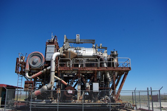
Several non-flightworthy prototype nuclear aircraft engines were actually tested at the Initial Engine Test Area, located at the north end of Test Area North. HTRE-1, also known as the Core Test Facility, the initial aircraft engine/reactor testbed, was mounted on a huge mobile railroad car assembly.
It was a water-moderated uranium reactor with a beryllium reflector & shielding that included large quantities of mercury. The two jet engines just visible at lower left would be started using hot gas produced by chemical-fuel combustors. Once the jets were running at speed, the reactor would be brought up to power & airflow would be established through the core.
Its heat would then be gradually diverted to the jet turbines as the gas combustor flow was phased out. The jets would be run on nuclear-heated air for periods of hours at a time to simulate the operation of a long-duration nuclear aircraft powerplant. Post-shutdown, the reactor’s railcar would be returned to a maintenance bay for disassembly & analysis. HTRE-1 reached power levels as high as 20.2 megawatts.
General Electric began HTRE-1 test runs in 1955 and the reactor successfully powered the X39 engines the following year, although the massive contraption was far from a practical aircraft powerplant.
However, HTRE-3 was a major step toward a flight-capable nuclear engine, which would have been designated XNJ140E-1. The dimensions of the core & its structural characteristics as well as the design temperatures were those of a power plant capable of providing useful flight propulsion. The power generated by HTRE-3 ranged up to 35 megawatts. In the HTRE No. 3 tests, the power levels were so chosen that the fuel element temperatures, the key parameter, would be characteristic of flight service. The size & configuration of HTRE-3 appear to have been designed with the B-36 or B-60 in mind. HTRE-3 was operated at the National Reactor Testing Station from 1958-60.
Although no aircraft was ever operated under nuclear propulsion, an NB-36 testbed did fly while carrying an operating nuclear reactor. These flights were not carried out from TAN, tough.
Having successfully operated a 35 megawatt, flightweight nuclear turbojet powerplant that probably could have propelled a bomber-sized aircraft, the Aircraft Nuclear Propulsion project came rather close to fulfilling the original design goals of the late 1940s. If HTRE-3 had existed in 1952, it most likely would have flown in an aircraft, but by 1961 the very existence of manned bombers was threatened by the cheaper, faster & relatively invulnerable ICBM. The large nuclear airplane engine had lost its raison d’etre in the Kennedy/McNamara era, and the ANP program was cancelled in 1961.
Today, Test Area North is composed of four areas:
The Contained Test Facility,
The Technical Support Facility,
The Water Reactor Research Test Facility,
The Initial Engine Test area.
The Contained Test Facility is located at the west end of Test Area North. This facility includes the Containment & Service Building (reactor facility), the aircraft hangar, the Reactor Control & Equipment Building, and numerous support facilities. Preparation for deactivation of these buildings & structures began in 1996, and included documentation of some of the historic properties, including the Nuclear Aircraft Hangar.
The Initial Engine Test area is located at the north end of Test Area North. After the Aircraft Nuclear Propulsion program ended in 1961, the area was used for the Space Nuclear Auxiliary Power Transient Program through 1967. Currently, the Initial Engine Test facility is being demolished.
The Three Mile Island Unit 2 reactor core was shipped to the INEEL’s Spent Fuel Program area in 1986. According to INEEL’s website, “Unless it becomes necessary for the US to resume former levels of defense-related activities, the future of Test Area North will consist of completing current programs, deactivating all facilities, and completing environmental restoration activities.”**
_______
Sources
† Herken, Gregg, and Ralph C. Merkle. “The Flying Crowbar.” Project Pluto. Merkle.com, n.d. Web. 16 Nov. 2014. .
* “.:SonicBomb:. – The Nuclear Powered Bomber.” The Nuclear Powered Bomber. SonicBomb, 3 Sept. 2010. Web. 16 Nov. 2014.
**”An Airfield Without A Runway.” An Airfield Without A Runway. 456FIS.ORG, 10 Feb. 2014. Web. 16 Nov. 2014.